Riley Einspahr: Architectural Design I
Project 01: Fibonacci Cube
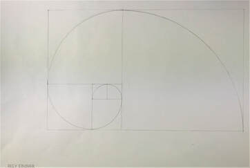
For the beginning of this project we started with learning how to properly draw a Fibonacci Spiral. This benefited us later on when we began to design our three plane models, which were step one of designing our Final Cube Model. This projection was an introduction into basic architectural design. Using the limitations of an 8 by 8 cube and the use of three plan models we were tasked with designing a versatile transportation stop.
Drawings and Model
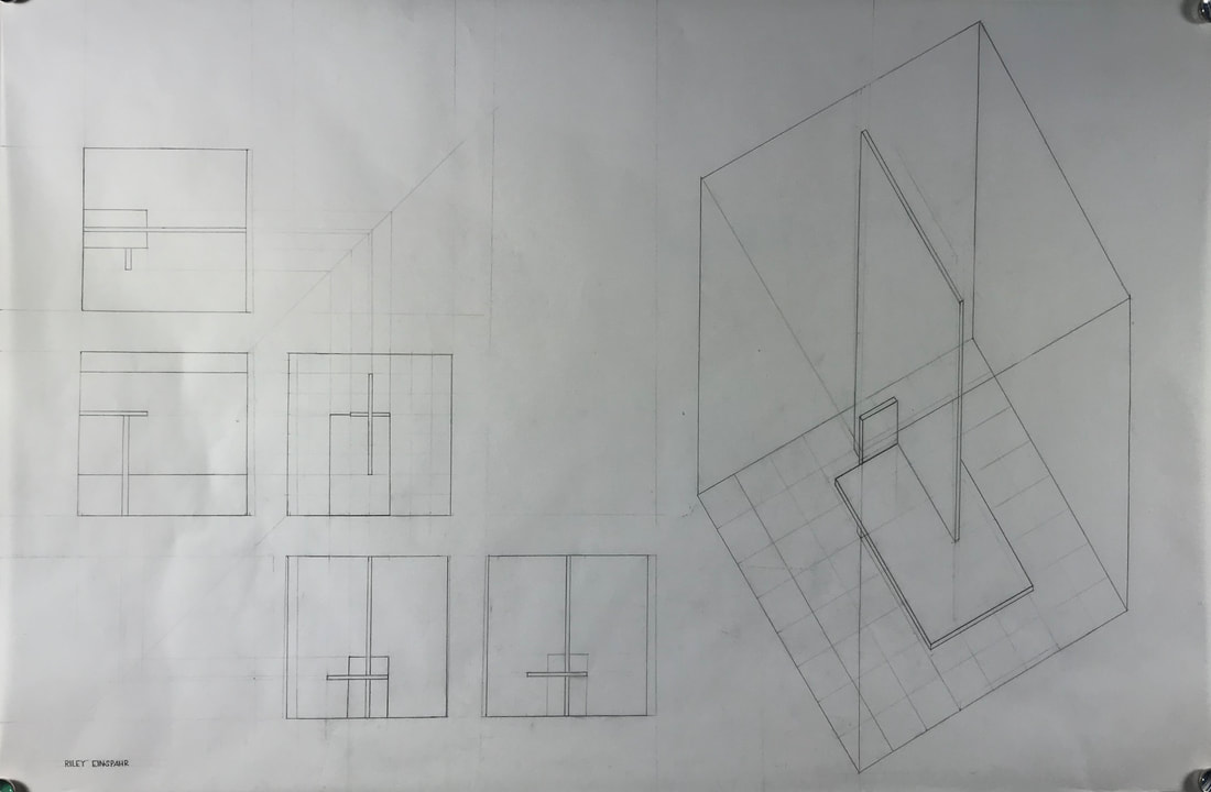
Plane Study Drawing
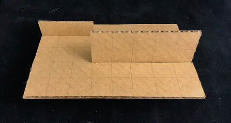
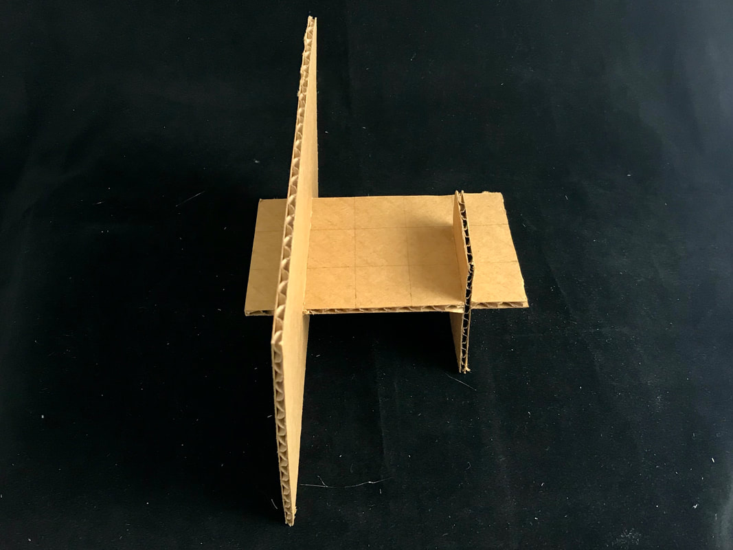
The design aspect began with the three plane models. Using certain sized planes we had to construct models that could act as platform for standing, sitting, or properly dividing space. We were also tasked with connecting the planes through interlocking connections. That means that the planes must be intersect into one another so that it would stand completely on its own, without the use of glue or other materials. When cutting our the three planes it was very important to be very precise with your cuts so that each edge would be even and every grid would be the same. If measurements had been off, the model would possibly not be able to stand on its own or would fit haphazardly.
|
Final Cube: Isometric
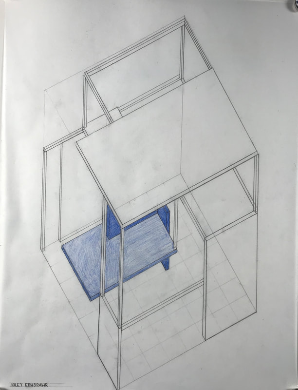
For the drawing of our final cube, we practiced our paraline drawing skills. We began the drawing with the outline of a 8 by 8 cube. Then we drew in each plan according to its position in our model. This drawing went a lot smoother than the first paraline drawing seen earlier in this project. Once we had completed the drawing we went in with a colored pencil to emphasis our original three plane model which we built the rest of the model around.
|
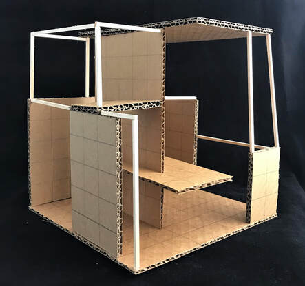
Final Cube: Model
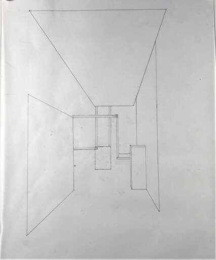
Final Cube: Interior Perspective
|
Project 02: Micro-Townhouse
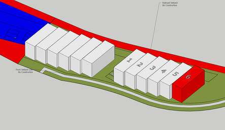
The site assigned to build the town house lays right outside of Old Town Lewisville. That means that small shops, restaurants, and stores are nearby for our customers. The site also backs up against a railroad. This will provide a easy source of transportation for the clients. Having the end location to design my town house has allowed me to enhance the design of my townhouse. Due to the open side I was able to add a side patio on the second floor of the townhouse and create more dimension.
Concept Design
My final design was the combination of many different elements from different concepts.
The first picture is of one of my first designs. From this concept I decided I wanted my house to be "offset" or have parts of it that were cut out to provide a Flemish Bond effect on the layout.
The second picture is where I developed the idea for an arched roof. This was to appeal to both my clients and architects appreciation for arches.
The third picture is the development of having my back patio take up half of my third floor. I wanted to provide enough space for my clients to have space for some outside form like a fireplace or covering.
The fourth picture is a combination of all of the ideas. The first two floors are offset, there is a curved roof that covers half od the third floor which allows space for back patio.
The fifth photo is the beginning plan for my floor plans. By making a bubble map of each floor plan I was able to see how the rooms would flow together and how spaces in the townhouse would be created.
The sixth and seventh phot are of my study Model. the main idea for this was to get a general idea of what my final model would look like, along with if the structure would support itself.
Final Design
The first there photos are drawings with the dimensions I would go on to use to build my model. The actual drawing is not to scale but I quick sketch from my scaled drawing in AutoCAD. From AutoCAD I got the correct dimensions so that when constructing my model I would have easy access to the dimensions.
The last three pictures are of my final model. From the windows you can see part of the floor plan within and you can see places where the building is "offset" or cut out. In the model you can see each part of the home come together. First, there is the cutout on the bottom left corner that lead to the door. This cut out also acts as a front patio area. Then on the second floor the walls only extant over 15 feet not 20 which allows space for an outside patio. Finally the walls only taking up half of the top floor creates an outside patio area.
I wanted arches to play a large role in my final design. I incorporated them through the shape of the roof along with windows in the front and side of the home. This was to entertain both my architects and clients fascination with arches. Also it cant be told by the model but the townhouse will be built with primarily bricks and a shingle roof.
