Project 01: The Fibonacci Sequence

For our project, we were assigned to create a cube based of planes that follow the Fibonacci Sequence. The planes were situated in an 8 by 8 cube to create the form of building structure. The Fibonacci sequence is represented by this spiral, which is divided into boxes of the ratio. This sequence can be seen not only in manmade structures, but nature as well, in snail shells and flowers.
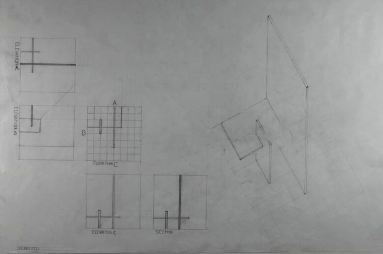
Plane Study Drawing
This Drawing was an exercise to prepare us for the future assignments. It taught us how to correctly plan our drawings, and taught us the several different forms of sketching a building, and how to sketch using these methods.
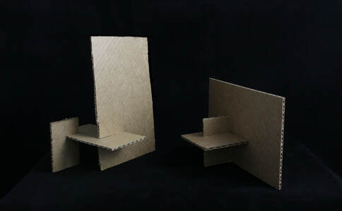
Plane Study Model
The plane study model was the basis of our entire project, and we based the entire project off of it. The planes are made based off the Fibonacci sequence, and they become rooms based on how you look at it.
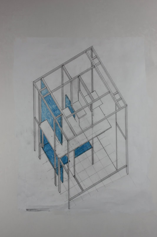
Final Cube: Isometric
|
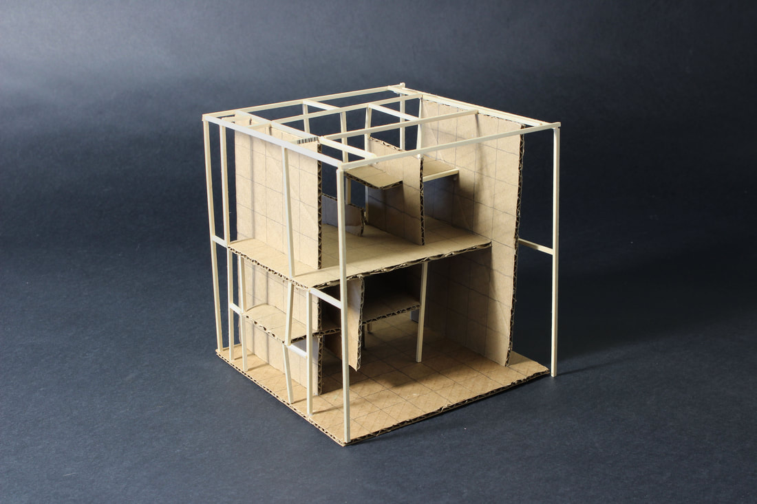
Final Cube: Model
The final cube is built off the original plane, and it can be formed into a building as well.
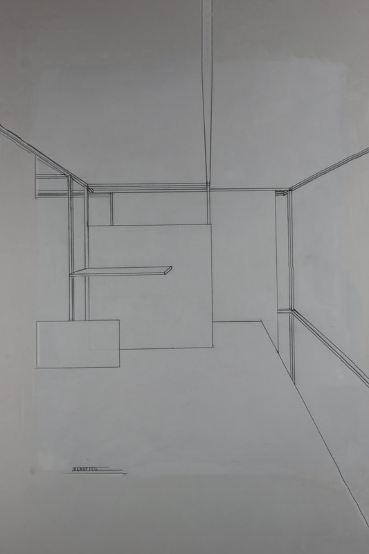
Final Cube: Interior Perspective
|
The Final Cube was represented on paper in two ways. The first was an isometric cube, which showed the full shape of it, and allowed it to be scaled down. The Second was a perspective drawing, which developed space and distance between certain planes. It shows a new "perspective" on the planes, and gives it a more building like aspect.
Project 02: Communication Tower
Project two took the Fibonacci ratio based cube from Project 01 and turned it into a habitable communication tower to be placed adjacent to the U.S. Mexico border wall. We attempted to create a tower for locals of the area to be able to communicate with the other side of the wall, which basically would eliminate the cultural impact the wall would bring upon the area.
AutoCAD
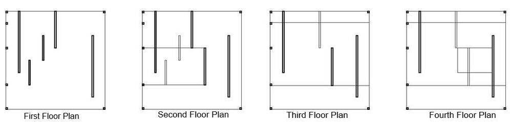
We began Project 02 by learning the basics of the desktop program "AutoCAD." The first assignment we were to complete were the plans for each floor. My cube had four separate floors, all represented by these plans in the image above. The darker lines represent the sticks and planes that were "cut through" to view that floor.
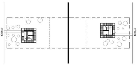
Also done in AutoCAD, my site is displaying the two adjacent towers, the space around them, the scenery, shrubbery, sidewalks, roads, and the wall itself. I positioned the trees in random locations (without obstructing the view of the tower, that is) and of random size, to create a more natural, random environment. Instead of a manmade, assigned environment, the tower is positioned right in with the natural environment of the area.

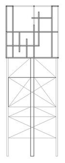
We created many things in AutoCAD, including our elevation drawing, pictured closest right. This includes both the created support structure, and the Fibonacci Cube. It is to develop depth using the line weight, and show what it would look like with the supports attached.
|
To the left is my section drawing. It is similar to my elevation drawing, as it includes the finial cube model, and the base and supports. The difference is that it is as if a cut went through the middle of the model, and shows the depth of the model from there. It shows the planes that were and weren't cut through. it is used to show the different openings and rooms of the final cube.
|
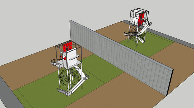
Sketchup
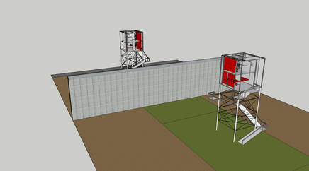
These are examples of my final Sketchup drawing, including the final cube, the supports, the walk up, and the border wall and site of the area. It is based off of the original cube, with minor adjustments to accommodate for space and aesthetics. It developed an idea for how it would work alongside the border wall, and being adjacent to the other tower, similar to the way the AutoCAD site had.
Final Models
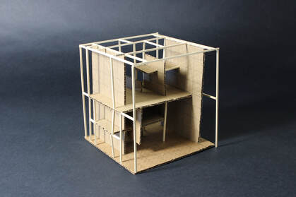
This is the same model from Project 01, which was still used heavily in Project 02. The tower is based of this model, and the other, smaller scale models are slightly adjusted versions of this original model.
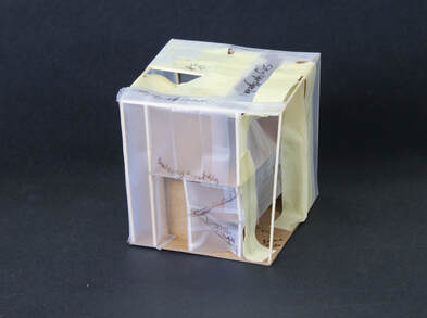
This is the study model used ultimately for the final model. It includes the adjustments I placed to create a more aesthetic appeal. It has notes written over it to show where I wanted to place stairs and entrances, and what each type of tape represented. The translucent (somewhat) tape represents glass in the structure, and the thicker tape represents extra planes and structures in the model. I went for a very aesthetic appeal, as I wanted it to be able to have lots of natural light let in, while still being practical.
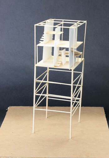
The picture to the left is the final model, built at 1/4 scale of the original, and done complete with the base, supports, stairs (though not the ones leading up), and the finished cube set on top. It is built in the same scale and layout as the study model, but it is built more out of balsa wood and sticks, instead of cardboard. It represents what the tower would look like if it was placed on the border. It is completed and it is down to the final quarter inch in where everything would be placed. This gave the audience and myself more of an idea of what it would look like if actually built, what is done right, and what could be done better.
