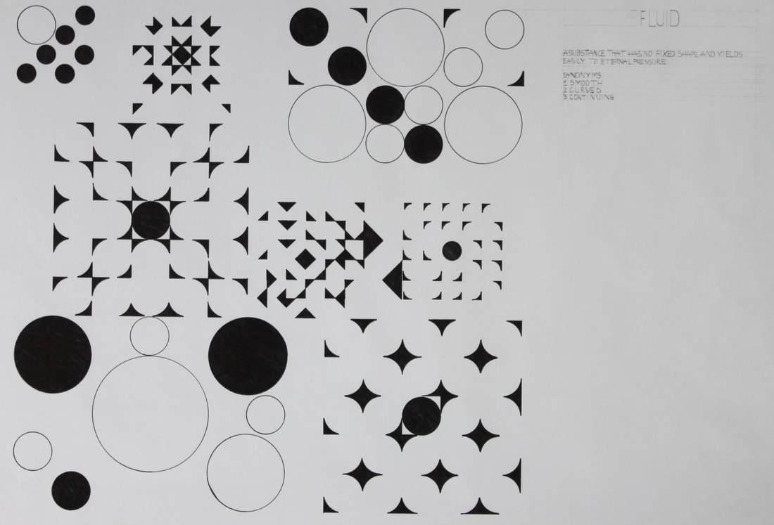
Laila Zamora: Architectural Design lThe concept that guided my inspiration and helped build the following designs was the word fluid. Which can be defined as "a substance that has no fixed shape and yields easily to external pressure". The word was interpreted into architecture by following the concept of the ripple effect, of how a single drop of water can change the form of it falling on a puddle of water.
|
GEOMETRY STUDY |
Starting off with the geometry study, which was the first project assigned to us. Where the objective was to create a geometry study based off of the following shapes, circle, square and triangles in a 13 x 13 grid. The concept I referred back to was the ripple effects, there is a distinct ripples found throughout the geometry study. Such as the center of the ripples and the “second wave” dictated the rest of the pattern of the ripple. Which correlates back to the definition of fluid as the paper being a puddle of water and the droplets of water are changing the form of the designs on the paper. |
Lake Michigamme, Michigan
|
|
Lake Michigamme is a tourist attraction in Michigan, as a great quantity of people enjoy canoeing, fishing, as it contains a great diversity of species in the lake. Lake Michigamme is made up of yellow birch trees that surround the area where the tiny house will be constructed. It is located in the city of Marquette, in that particular area it snows mostly all year from October all the way to may with an average of 183 inches of snow per year.
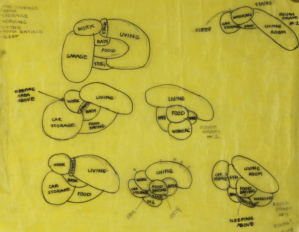
BUBBLE DIAGRAMMoving on the first step of designing a tiny house was to construct a bubble diagram to get a basic layout of the house and to have a better understanding of the structure of the floor plan. I incorporated the word fluid by having my design parti being “the fluid motion of attainable and unattainable spaces. Meaning having a certain space of the tiny house that wasn’t as within reach from the rest of the spaces.
Out of all of the sketches, the best one that followed along with my concept was the top left one. Which left the loft that can only be accessed through the office "unattainable". |
|
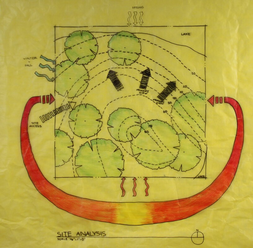
My site analysis was based off the location I picked in Marquette, Michigan, I choose this particular area as there is a lake (Lake Michigamme) located there. My site plan analysis helped determine where spaces of the house would be located, such as the views, wind patterns, sunrise and sunset as well as the trees. Such as the hot winds would be coming from the south, and the winter wind as well as the fall wind would come from north-west. Which is a factor I included while designing my tiny house as to have specific areas where there would be windows or opening sliding doors for the wind to enter through the house. |
SITE ANALYSIS |
|
Marquette, Michigan Site analysis
|
LAYOUT |
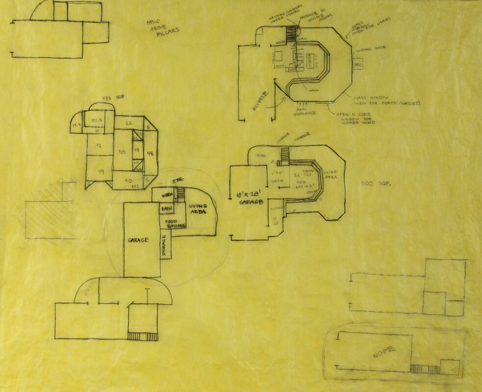
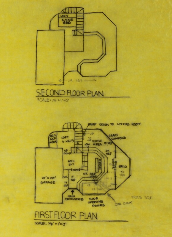
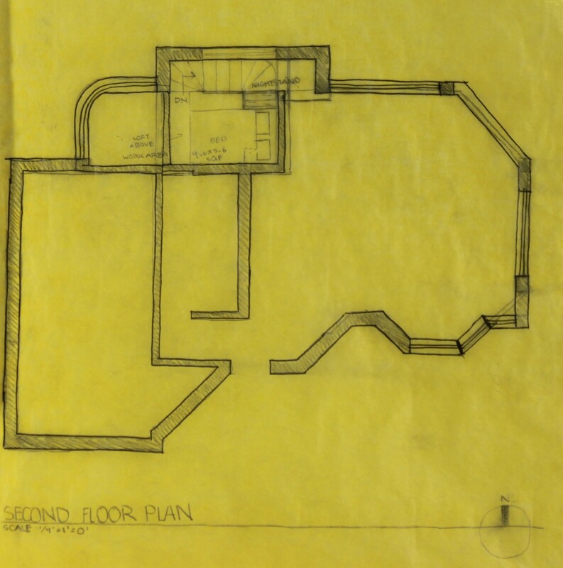
I aimed to construct a tiny house that its floor plan didn’t consist of a particular shape, such as a square, rectangle,etc. I related back to the bubble diagram to know where the spaces would be located as well as referring back to my design parti. The loft/sleeping area would only be able to be accessed through the office area and not in any other area. Whereas the rest of the spaces such as kitchen, living, office, etc. would be attainable and within reach of the spaces nearby. |
FLOOR PLANS |
Moving on the floor plans, I incorporated the views from the surrounding area which include Lake michigamme as well as the yellow birch trees that are within the property line. Going back towards my design parti of the fluid motion of attainable and unattainable spaces are evident on the floor plan as the stair that lead to the sleeping area located above the office are can only be accessed in the office. The living area captures a major view of the lake through its glass windows, moving towards the patio which is across from the kitchen also contains a view of Lake michigamme. The office as well as the stairs that lead to the sleeping area contains glass windows in order to capture a view of the lake. The space to the right of the main entrance has sliding opening doors to capture the hot winds coming from the south as well as it serves to capture a view of the yellow birch trees. The floor plan on the left side was drawn on a 1/8 inch scale as well as the elevations below. |
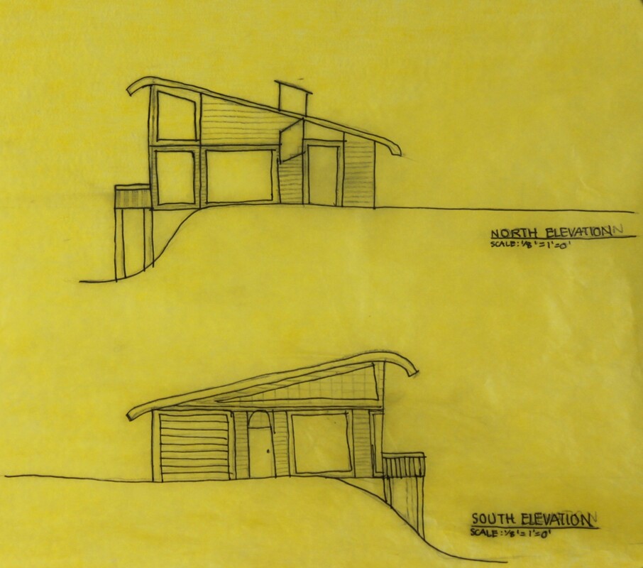
ELEVATIONSFollowing the floor plans designs it then created the structure for the elevations of the tiny house. The elevations only show the sides of the house in detail, no 3D dimensions are shown in elevations. Relating back to the site analysis, I had to be aware of the counter lines, since my design crossed over counter lines there would have to be support on the east side of the tine house in order to support its structure. A concrete foundation would be holding the patio as well as part of the house on the east side.
|
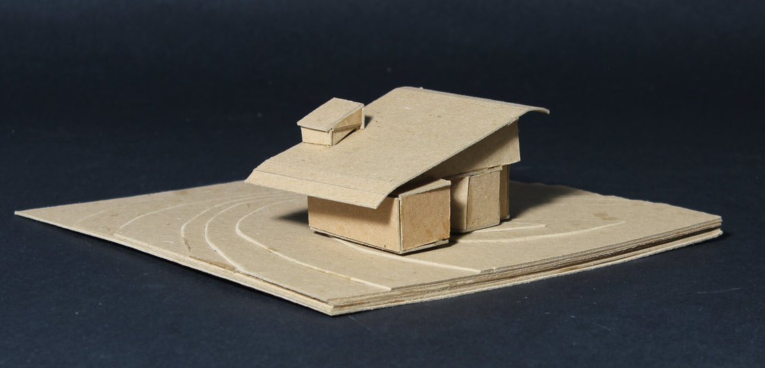
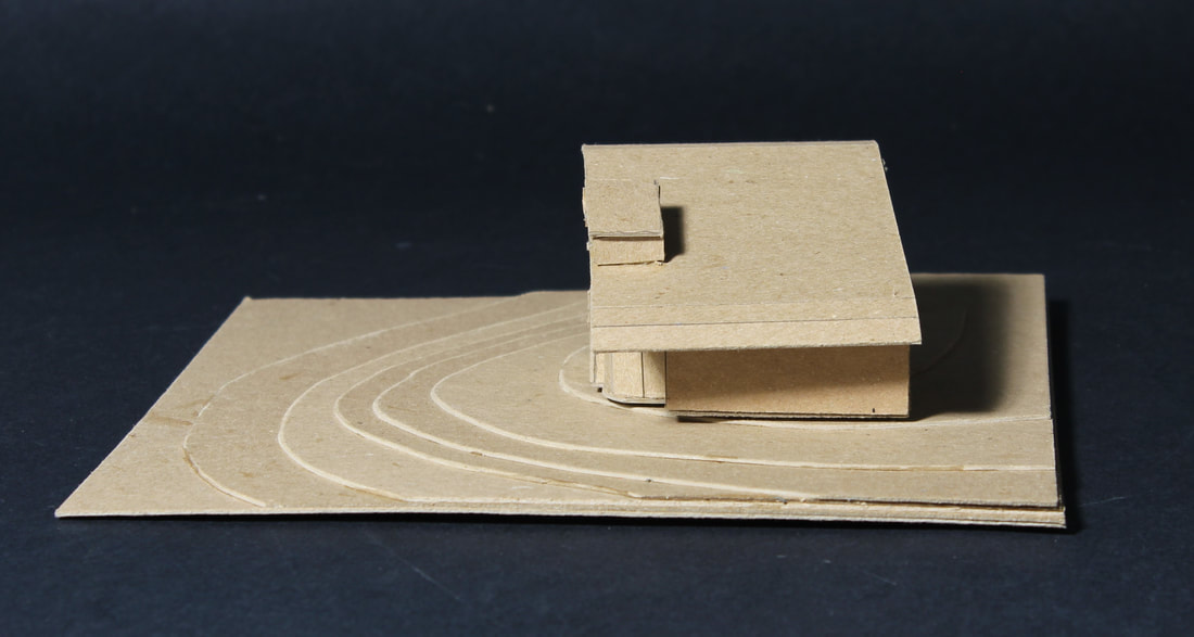
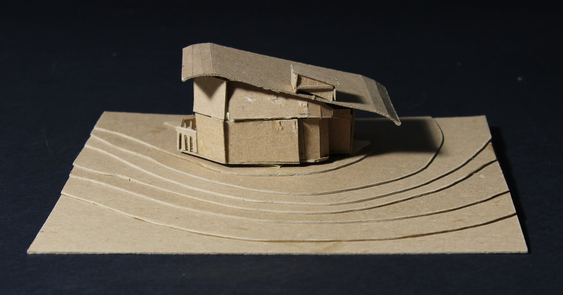
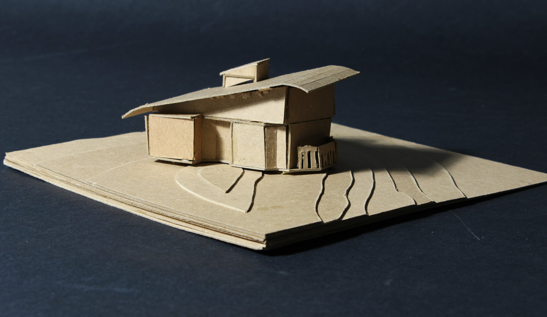
3D ModelThe pictures on the left represent my 3D mass model that is made up of chipboard. Based upon the floor plans as well as the elevation designs of the tiny house, it then helped to construct a 3D mass model along with the design of the roof. As well as to have an understanding of how the tiny house would align within the contour lines to further adjust the elevations.
The slanted roof was intentional in my design as in that Marquette, Michigan, it snows for more than half of the year, which makes sense to have a slanted roof type so that the snow can slide off and not accumulate causing damage to the house. Having a 3D mass model helped me have a better understanding of how my design would look like as well as to make further adjustments to my elevation designs. |
|
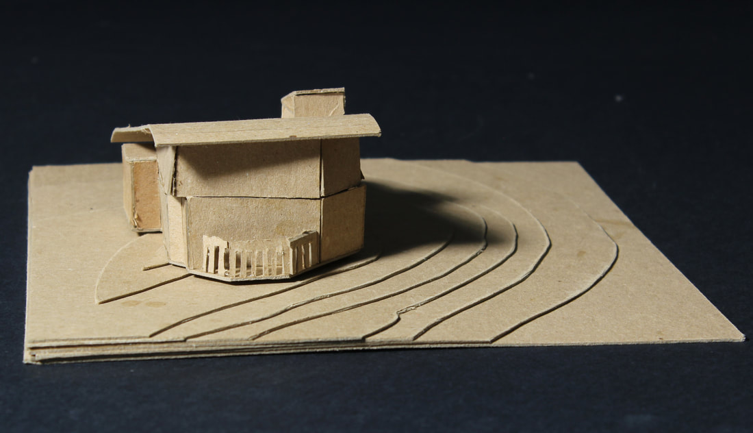
Continuing on more perspective angles it gives us an understanding of the structure of the house and how it can correlate with the environment. One major goal I kept in mind while designing the tiny house was to capture as much views as possible of the environment. It is evident in the mass model as there are glass windows in the living area which is on the left side near the patio in the first mass model picture.
In addition to capturing views, another major goal was to capture as much natural light as possible. The roof is designed to have glass windows above so that the light from the sun would be directed towards the kitchen area as well as the living area. However, the roof type for the loft/sleeping area does not contain any windows in order for the person to not be awakened by the sun. Nevertheless, in the afternoon when the sun is towards the west side, light would then be directed into the loft by windows on the west side. |
CONTINUING FLOOR PLANS
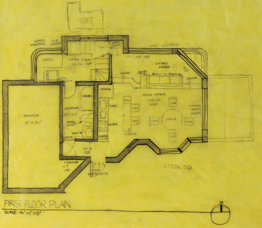
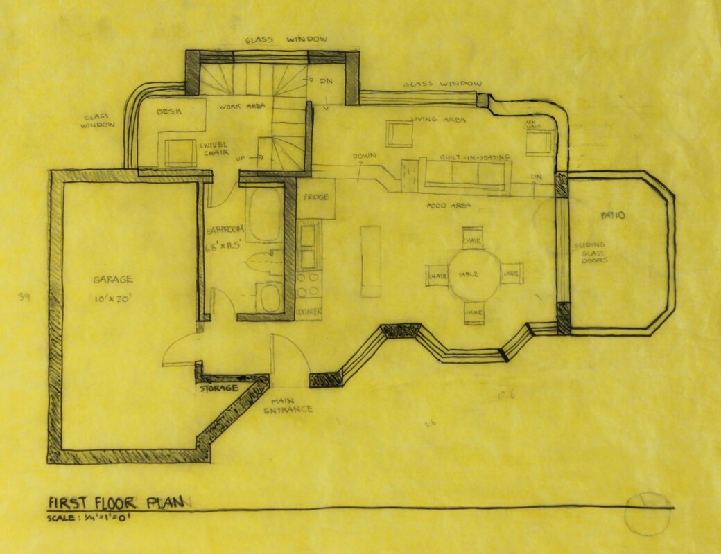
The floor plans below are drawn into 1/4 inch scale rather than 1/8 inch scale as the floor plans that are above. After receiving feedback, I took notice of how the stairs that lead to the loft didn’t match up with its purpose of having a passage under the stairs which was then corrected into the floor plans below. Previously in my initial floor plans there was either little to no space for the living area as well as the food area, to which I corrected it by extending both spaces further. I also improved the stair area by adding additional stairs to make space for the passage under the stairs that leads to the living area.
While also focusing on improving spaces from the initial floor plan, furniture then had to be implemented into the floor plan, which then adjustments had to be made in order to meet the furniture measurements into the spaces. Such as the bathroom had to be extended in order to fit the sink, water closet, shower. The living area had to be extended in order for a couch, seats, stool,etc. to be able to fit while also having enough space to travel through the spaces. While designing the furniture into the floor plans, a requirement that had to be met was that there had to be a minimum of 3 feet to pass through hallways or spaces. Furthermore, I had to also keep in mind of the measurements of the walls, which included the exterior, interior and plumbing as well.
While also focusing on improving spaces from the initial floor plan, furniture then had to be implemented into the floor plan, which then adjustments had to be made in order to meet the furniture measurements into the spaces. Such as the bathroom had to be extended in order to fit the sink, water closet, shower. The living area had to be extended in order for a couch, seats, stool,etc. to be able to fit while also having enough space to travel through the spaces. While designing the furniture into the floor plans, a requirement that had to be met was that there had to be a minimum of 3 feet to pass through hallways or spaces. Furthermore, I had to also keep in mind of the measurements of the walls, which included the exterior, interior and plumbing as well.
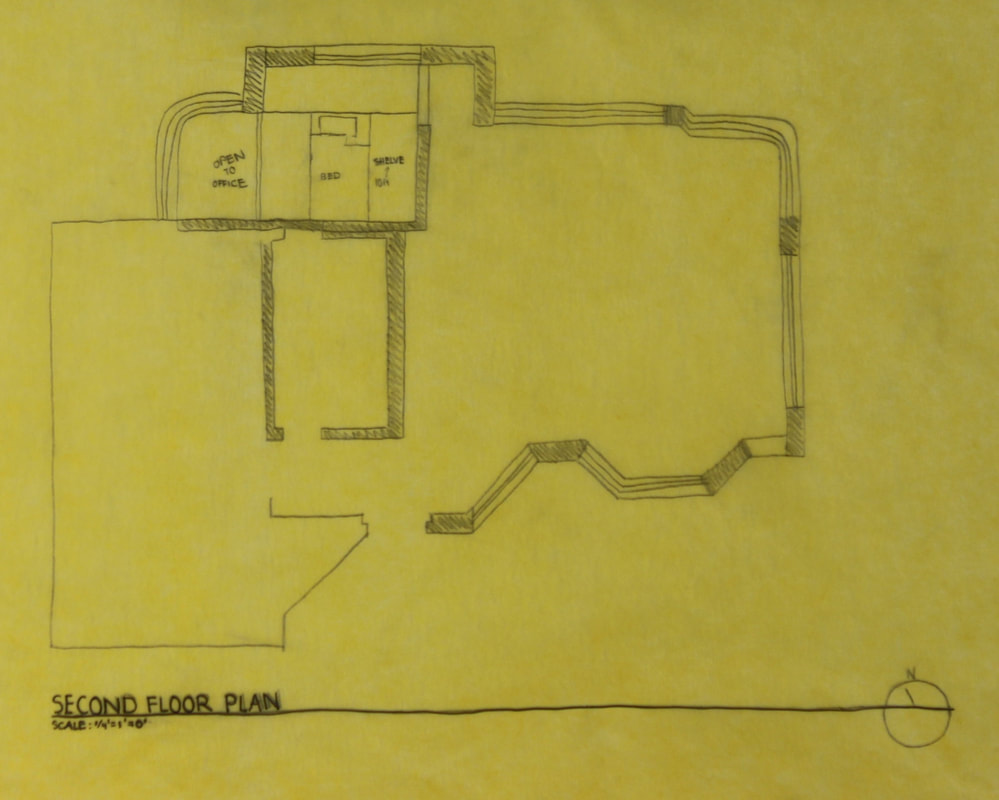
My final floor plans are shown above, some changes I implemented was the change the way of the door openings in the main entrance as it is designed to open inside and not outside. A door was also applied in the garage to the passage near the main entrance so that the storage area could be accessed within the house. Which relates back to my design parti of the fluid motion of attainable and unattainable spaces as the storage area can only be accessed through in the garage.
Moreover, the patio design was also adjusted to a different shape, the living area exterior walls were also adjusted so that an additional arm chair could be placed there to increase the number of people that could be in the living area. The passage under the stairs in the office area was also adjusted so that there could be steps instead of a ramp.
On the second floor plan, I changed the bed side as well as the way it would be placed on the sleeping area, on the right side of the bed is a shelf that 3 feet from the floor. This was intentionally designed so while the person is going up the stairs they would have enough space from the top to pass through.
In Progress Elevations
|
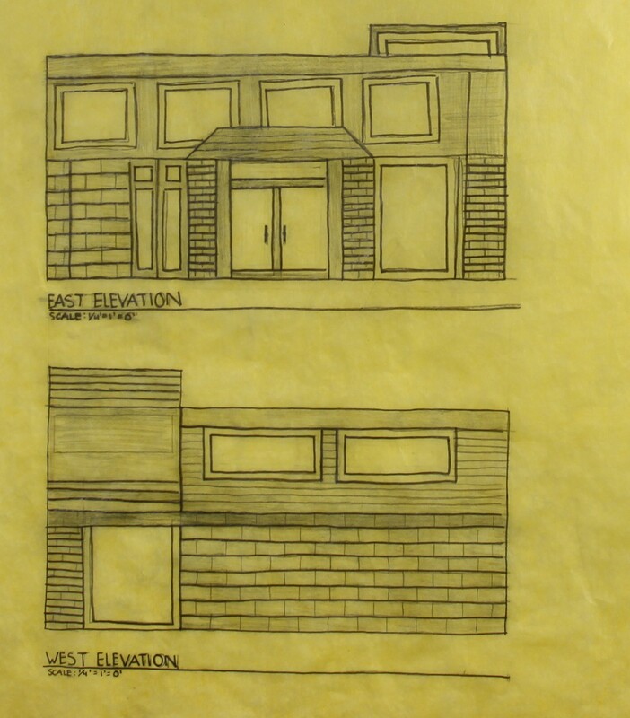
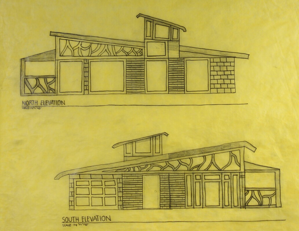
In accordance to the new adjustments that were made to the floor plans, the elevations adjusted as well. Glass windows were added on the east elevation in order to meet on of my goals of capturing as much natural light as possible. It is also evident on the west elevation as there are glass windows located on the roof to capture the mid-day sunlight.
As shown in the photographs, concrete blocks are used for the garages exterior walls on the west elevation, whilst bricks are used for the rest of the exterior walls excluding the areas that have glass windows and the roof. |
|
Referring back to my initial concept in the beginning of the ripple effect, of how the initial start of the water droplet changes the shape of water and dictates the rest of the ripple pattern. I implemented that concept into the roof type, the sleeping area's roof top would be the initial droplet making the roof of the rest of the house the same design.
Following up on the triangular glass shape above the main entrance, the curved lines are metal and are intentionally designed that way as the word "fluid" means a substance that has no fixed shape. In addition to capturing the views, glass windows are structured into the living area and the food area as well, the living are having a view of the lake while the food area has a direct view of the yellow birch trees. |
AutoCAD Elevation
Finalizing the project ended with drawing the elevations of the tiny house in AutoCAD, which is a program that allows you to draw and construct figures to create any type of drawing. In this scenario it was used to draw the elevations in a more clearer view and more accurate than on paper.
Adjustments were made to the elevations of the tiny house as there was an issue with the lack of space in the living area. This problem was addressed by increasing the area while also following the ribbon shape. |
|
Updated Floor PlansIn the final floor plans it is evident of the major change in the living area as it was extended towards the north side in order to create a bigger space to walk around in the living room as well as have an enlarged view of the lake than it was in the previous floor plan. The area will still be surrounded by glass to capture the intended views for that area.
|
|

