Rota Island Resort Project: By Joseph G. Purcell
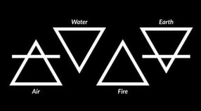
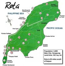
The goal of this project was to design a resort in a location of our choice. One of the main criteria of the project was to incorporate the four Greek elements (Earth, Water, Air, And Fire) into the design and layout of the resort.The location of my choice was Rota island, which is part of the Mariana Islands and is situated directly above the island of Guam. |
|
|
Early Layout Development:
|
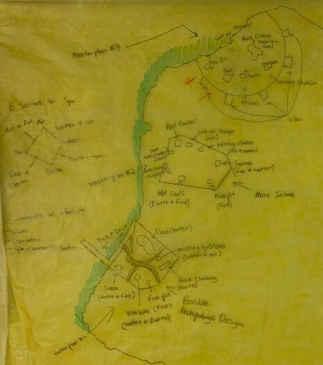
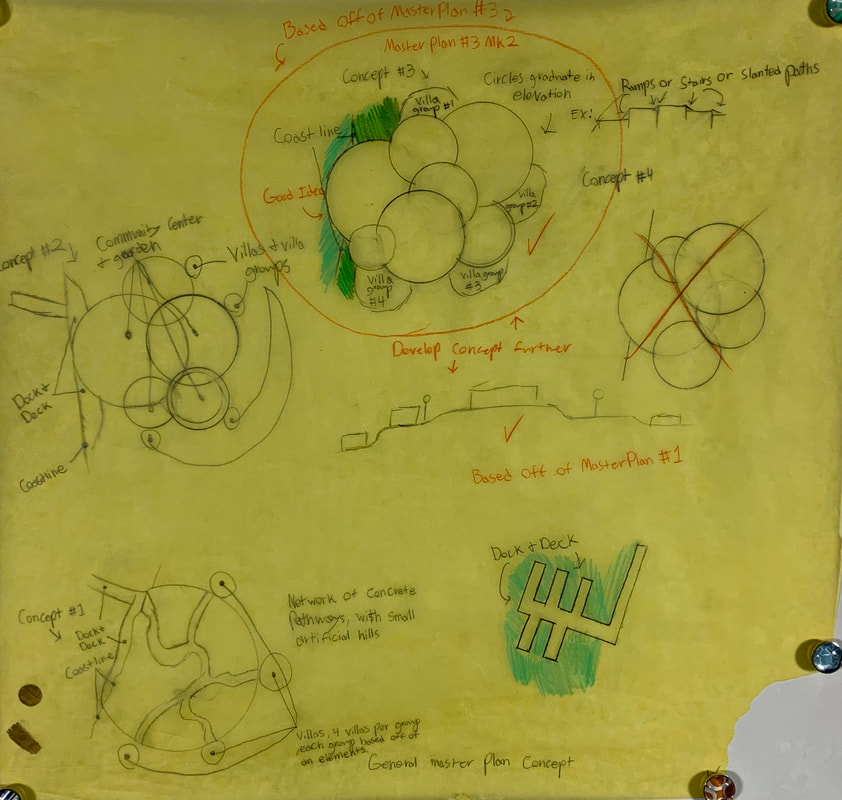
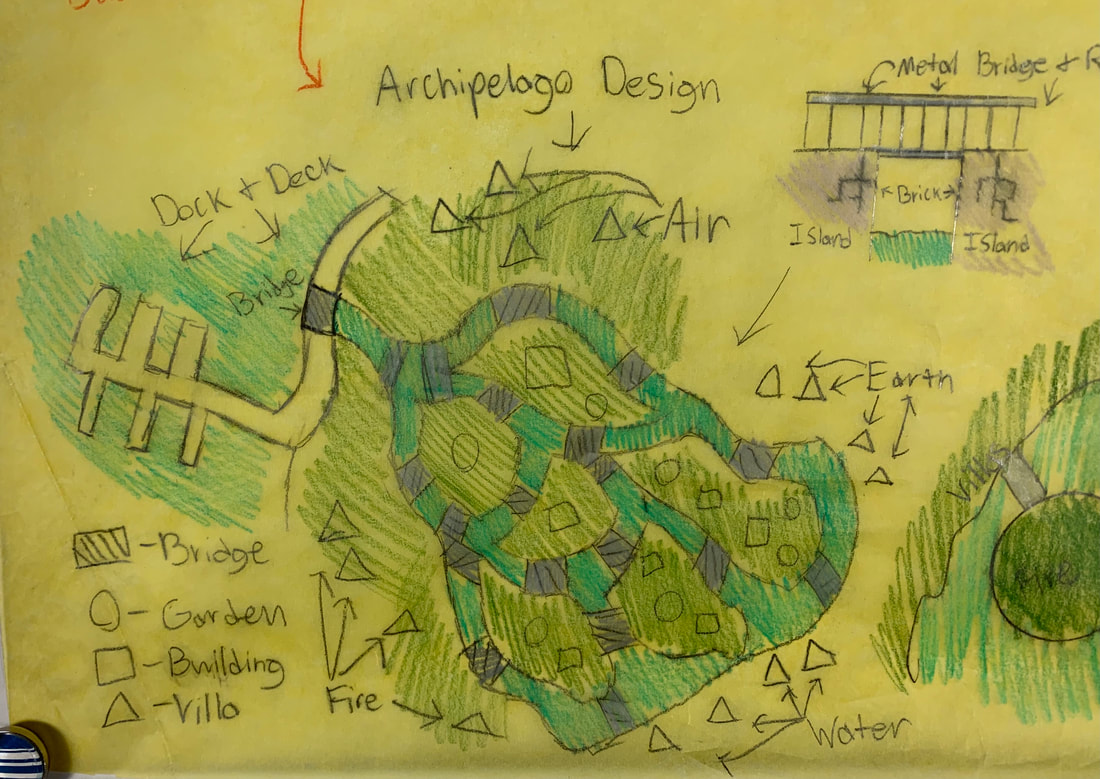
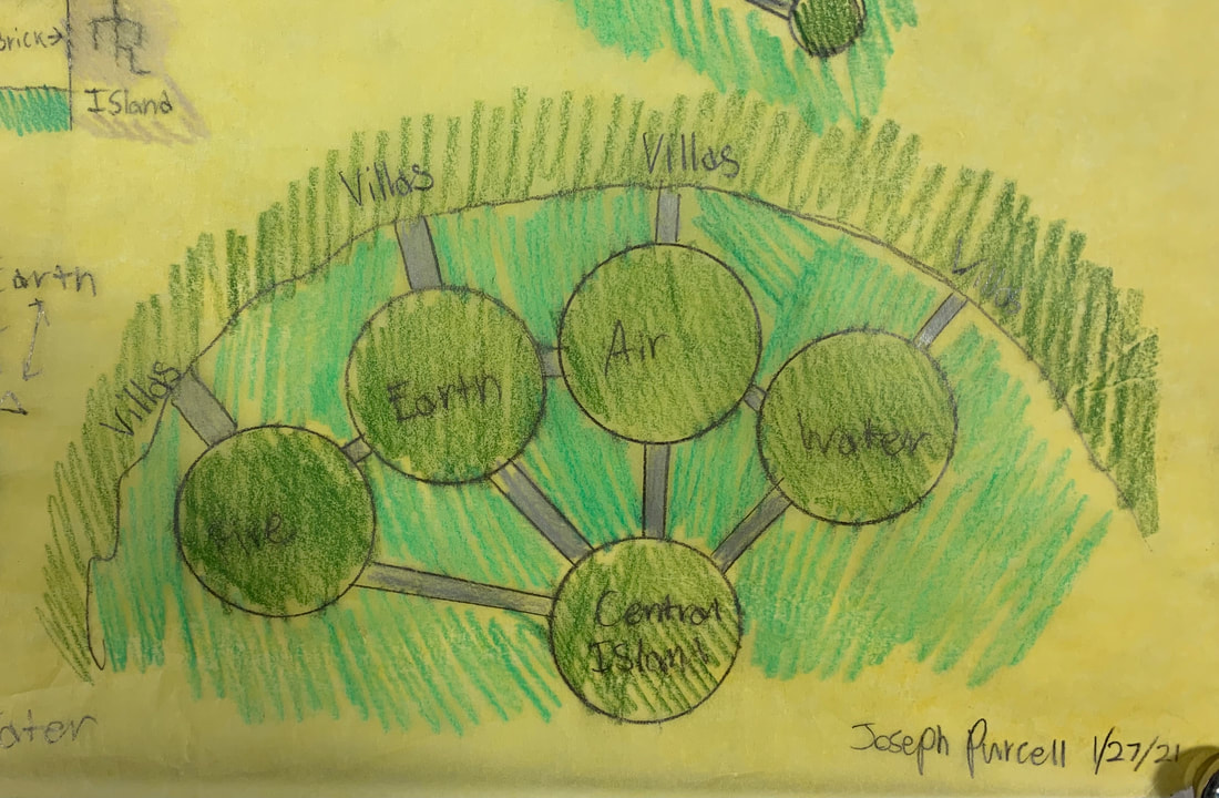
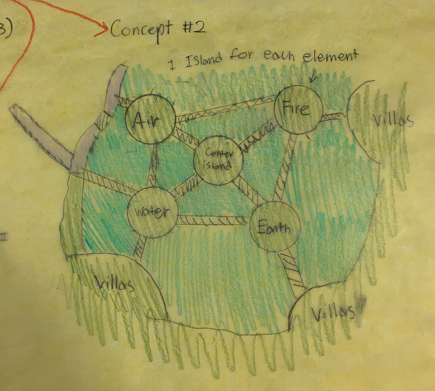
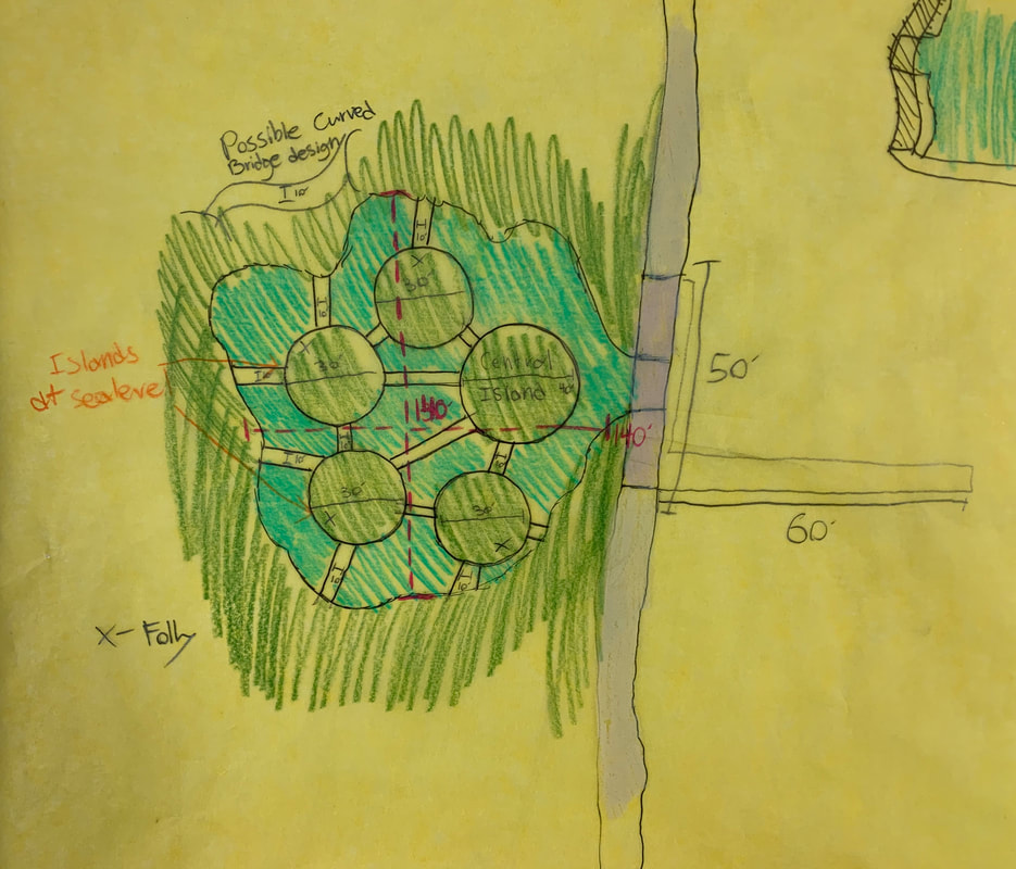
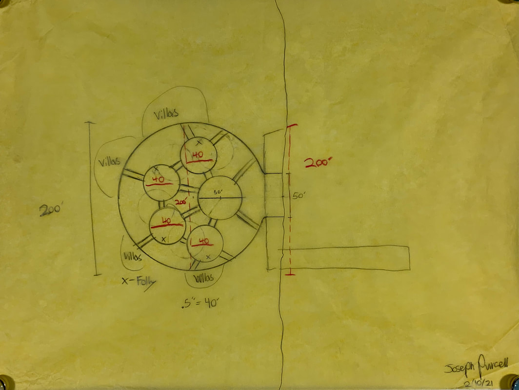
This is where the general layout of the resort would be initially designed. I had 2 general concepts that I used throughout the whole design process, 1. To have the garden and community areas of the resort to be combined, and to have the villas be on the inland edge of the Garden/Community area, and 2. To have the resort be on the shore and for it to have a dock and deck, as well as having it be close to the airport, allowing for easy access to the resort either by boat or by plane.
The third design at the top of the drawing below the map would ultimately become the concept that would gradually evolve into my final masterplan and layout.
|
|
Further Development of Masterplan #3:
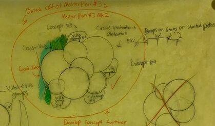
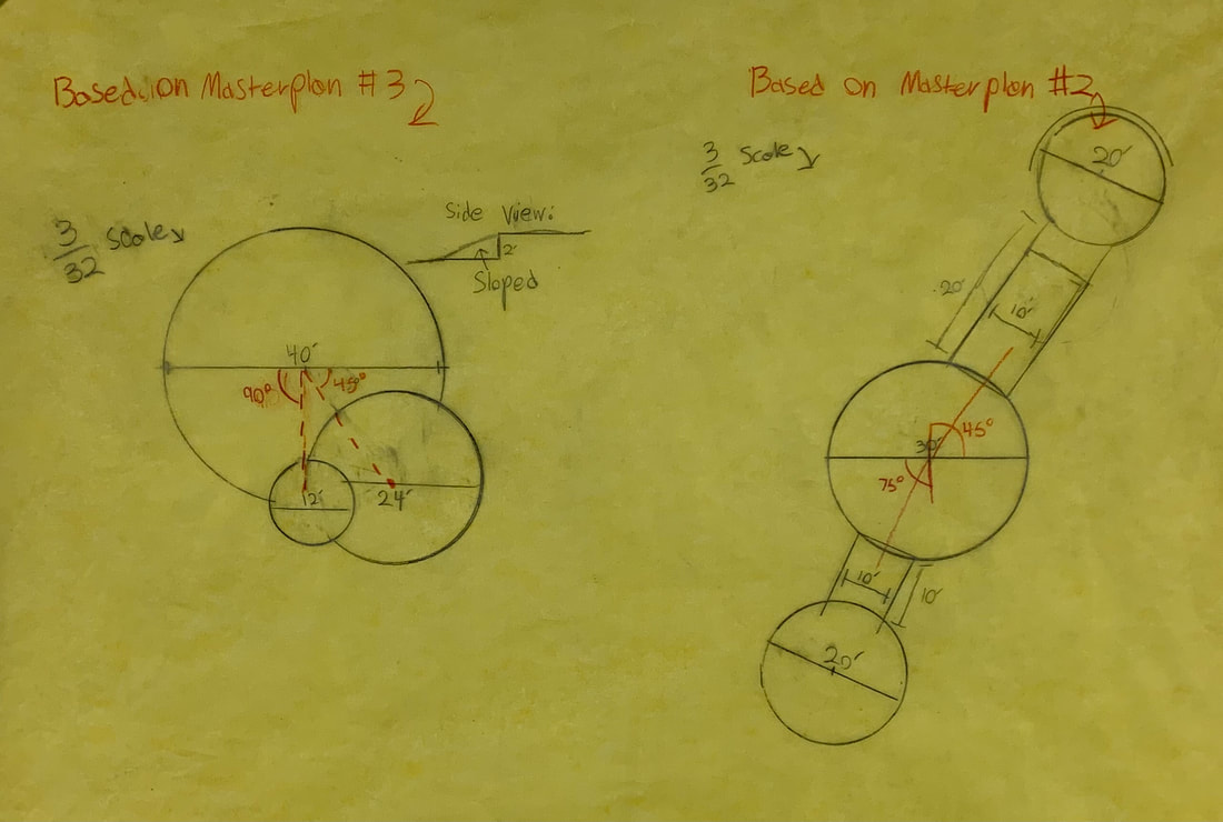
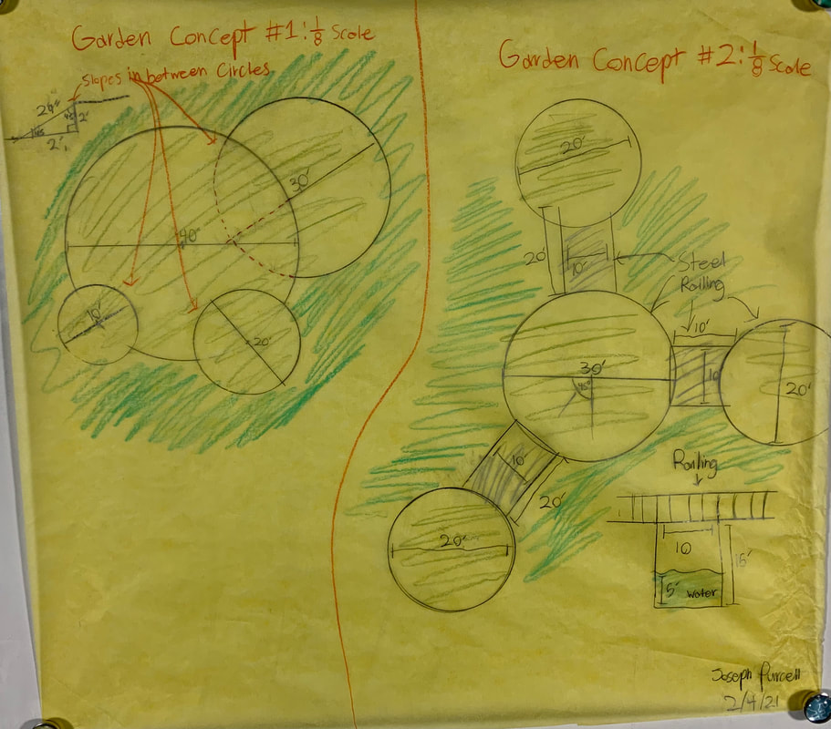
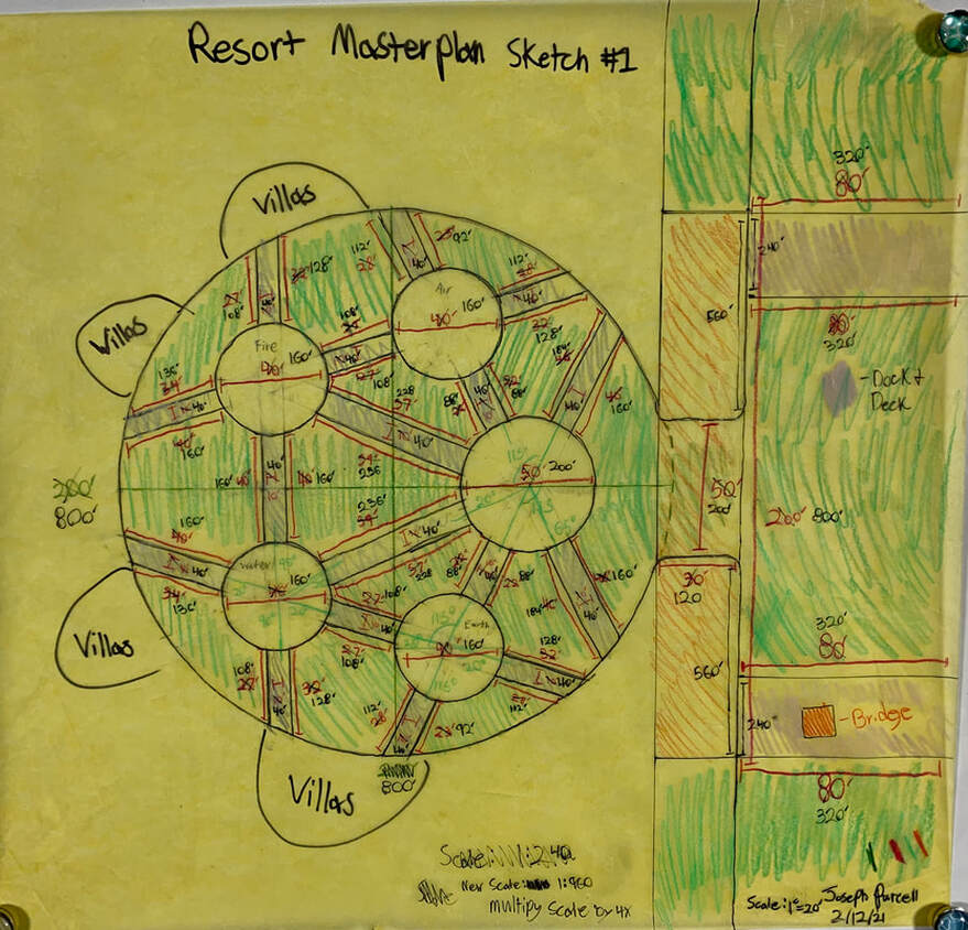
The second revision of Masterplan #3 would have the garden/community area be comprised of a series of flat "hills", each "hill' would be at a different level, and the "hills" would slope in between each other through a series of small and gradual ramps. This design was partially inspired by the rice terraces of rural China and rural Indochina. The idea of separate platforms would carry on into later designs of the garden/community area.
Masterplan Evolution Photo Gallery
Below is a gallery of the gradual evolution of the design of the garden/community area (pictures in order of left to right, top row to bottom row.)

Final Masterplan Design
Folly Design and Development:
|
Another requirement of our project was to design a Folly (or decorative building) for each element (Fire, Earth, Air, and Water). This portion of my page will go over the development and evolution of each respective folly.
|
|
Water Folly
Water Folly: Original Design
|
For the first design, the idea was to have water flow out through the small flat dome shaped apparatus at the top. this would then cause water to flow down the side in between the diving fins (colored red). The water would then fall down into the base at the bottom, which would then be pumped back into the apparatus at the top. This design was to convey the idea of a waterfall and the idea that water is almost always in motion. This design was abandoned after realizing that this folly was no different from a traditional water fountain.
|
|
Water Folly: Second Design
|
For the second design, I wanted to keep the concept of water almost constantly being in motion. First, water would be pumped out through the inner wall of the base and run down the spiraling channels and into the bottom of the smaller base in the middle, the water would then be pumped up into the top basin. the water would then pour out of the top basin through the six spigots, water would then both pour from the spigots to the basins directly beneath them as well as down into the basins in a spiral formation. This design was also abandoned after realizing that it was still separating people from water, and therefore not having people relate to the element itself.
|
|
Water Folly: Final Design
|
For the final design, I wanted to the folly to not just be a traditional fountain like the last two designs. I also wanted the physical appearance of the folly to be more representative of water. I finally came up with a water drop shaped pavilion and water ripple shaped base. The folly would work by having water located within the innermost ripple. The level of the water would be just above the top step of the circular steps in the base. Waterproof LEDs would be placed within the floor along the bottom of the inner wall of the drop. On the molding along the doorways and bottom of the outside of the drop in between the doorways are small vents. Behind these vents would be pumps that suck in water at the bottom, pump it up to the top through pipes embedded walls, and feed the water into a large atomizer located at the top of the inside of the drop. The atomizer at the top would turn about half of the water into a fine mist which would then slowly fall back down on the inside. The other half of the water sucked up into the top would then be dispensed back out through tiny slits located around the bottom of the small ball at the top of the drop, this would cause the water to pour down along the sides of the drop, creating a curtain of water for all four doorways of the drop. I feel that this design perfectly succeeds in representing its respective element both in terms of demonstrating the physical properties of water and in terms of aesthetically representing the appearance of water.
|
|
Fire Folly
Fire Folly: Original design
|
The original design for my fire folly was to make a cone of colored glass, this glass would be yellow at the bottom and gradually go to red at the top. Inside this giant glass cone would be a smaller glass cone of white frosted glass, and inside this smaller white glass cone would be a long pole comprised of bright LEDs that would pulsate in brightness to give the appearance of a flickering flame.
|
|
Fire Folly: Final Design
|
For the final design, I decided to convey the idea that when fire is in control, it can be used as a too, but when fire is out of control, it can destroy us. In the middle of the base (yellow) is a firepit, which will be gas powered. The decorative adobe (blue) will surround the firepit (representing fire being in control). The giant glass cone (red) will be comprised of steel pipe and colored glass (yellow at the bottom and gradually going from yellow to orange to finally red at the top). This giant glass cone will be place both the firepit and the adobe, the colored glass of the cone will in theory create a stained glass effect. This will cause everything in the glass cone to look various shades of yellow, orange, and red, giving off the illusion that the the adobe is on fire (representing fire being out of control).
|
|
Air Folly
Air Folly: Original Design
|
For the original design, I wanted to convey the idea that although you cannot see the air itself, you can see its effects on the environment around you. The first design called for a series of five wheel-shaped frames made of lightweight aluminum tubing. Each wheel would have four sets of canvas sails, this would, in theory, cause the wheels to spin in the wind, in a similar fashion to an anemometer. The wheels would also be on ball bearings and would be able to spin independently of each other. The design choice of having each wheel be smaller in diameter that the wheel above it was chosen to give the folly the illusion of looking like a small tornado or vortex while in motion. I felt like this design was too basic in my eyes and that it didn't really convey my idea the way I wanted it to to be conveyed.
|
|
Air Folly: Final Design
|
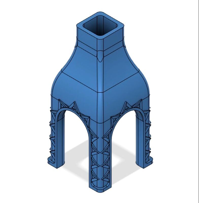
The final design utilizes a tensegrity table for the base, a tensegrity table works by having having all of the chords (colored red) be in constant tension with each other, thus causing it to "float". I chose to make the base of my new folly a tensegrity table because I felt like it better represented the first half of my idea of not being able to see air. It also helps with the second portion of my idea by making it appear that the air itself is a building material of the folly. On top of the folly, there will be a light weight aluminum screw that will spin in the wind. I felt that this design better conveys the idea of not being able to see air, but being able to see its effects on the surrounding environment.
|
|
Earth Folly
Earth Folly: Original Design
|
For the original design, I wanted to convey the idea of earth being this solid and rigid material that can take on many different forms and how people can interact with these different forms in many different ways. The original design would consist of a concrete cave with rock climbing holds lining the inside of the cave, allowing people to climb along the inside of the cave, people could also walk through the cave. I decided to change the design of the folly because I felt like you couldn't interact with it enough, you could either walk through it, or climb on the inside.
|
|
Earth Villa: Final Design
|
For the final design, I decided to add a pair of steps/ladder to both sides of the folly. This would allow people to climb to the top of the folly like a mountain. (The little chevron shapes on the underside are to represent rock climbing holds) This design will allow people to interact with the folly more. People can now climb on the inside of it, climb on top of it, or simply walk through it.
|
|
Master Plan Model
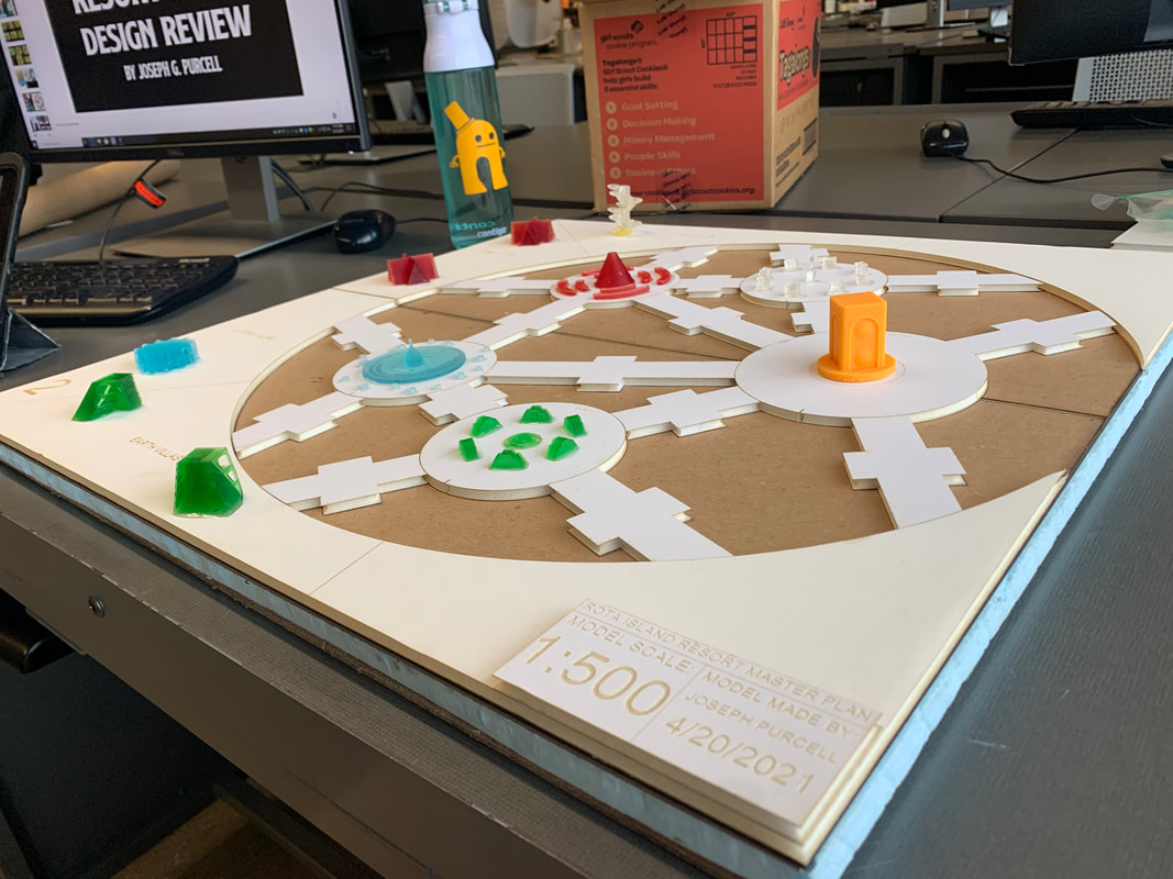
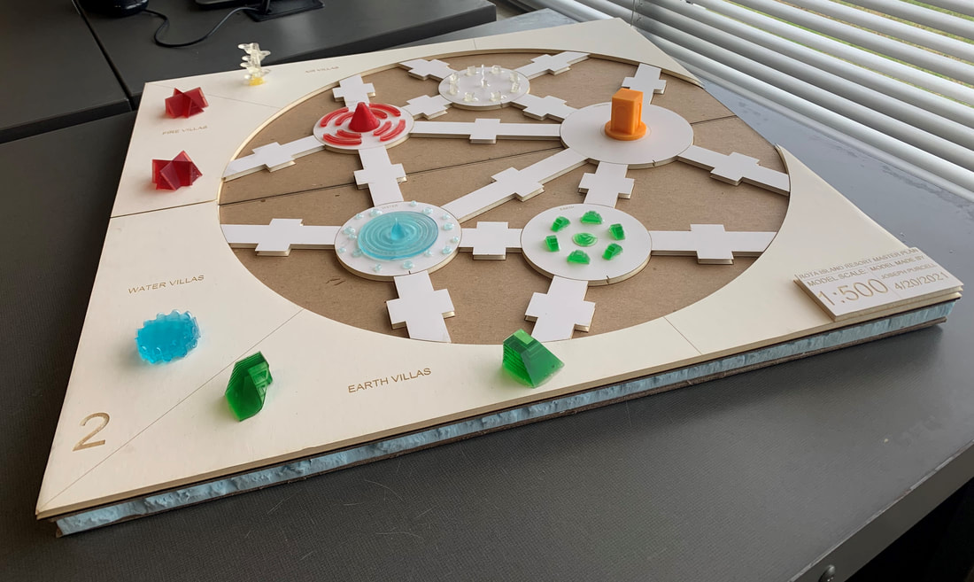
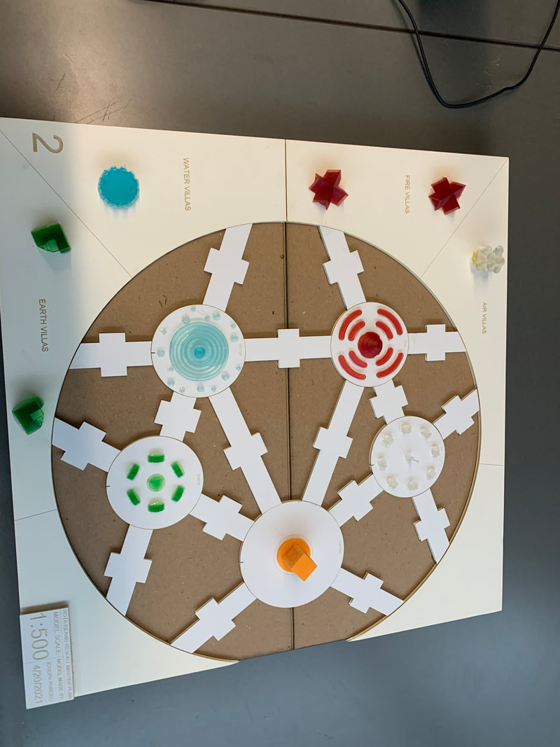
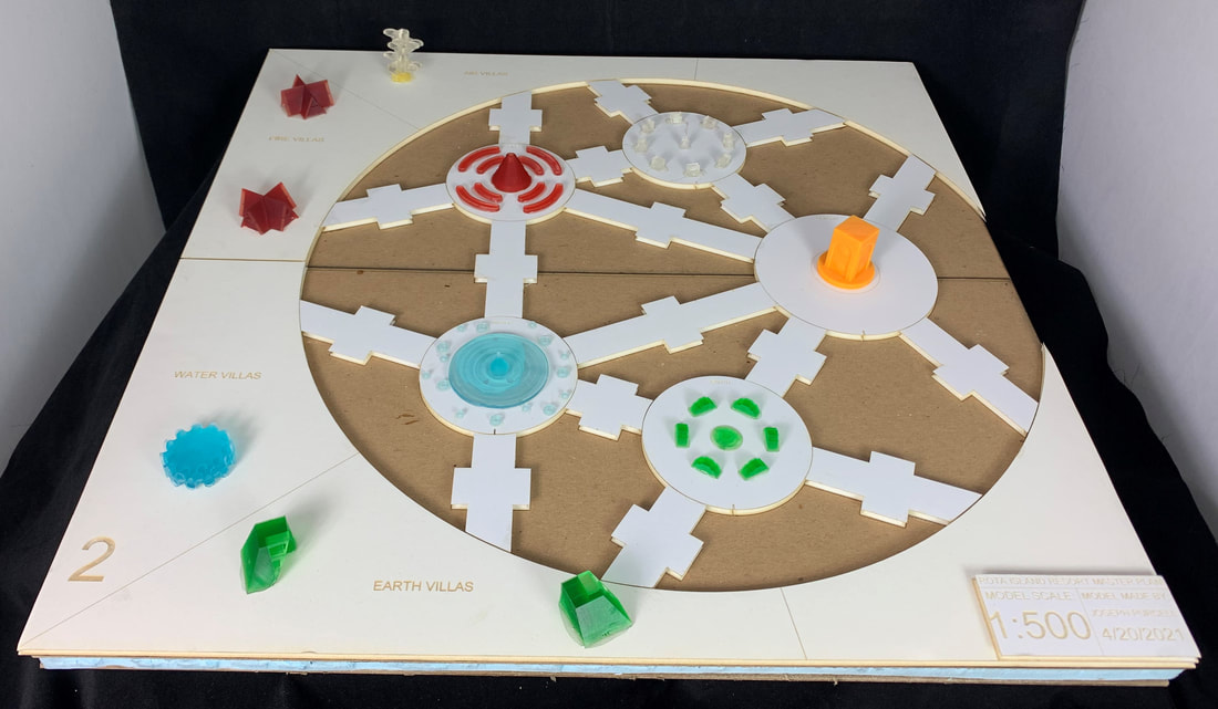
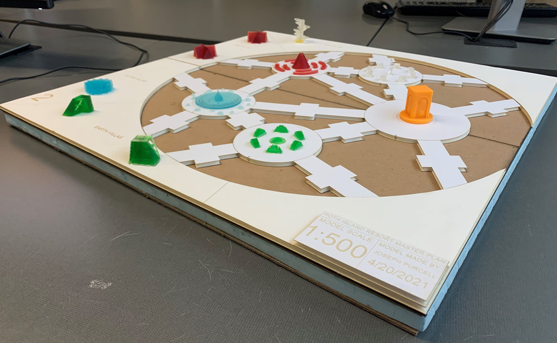
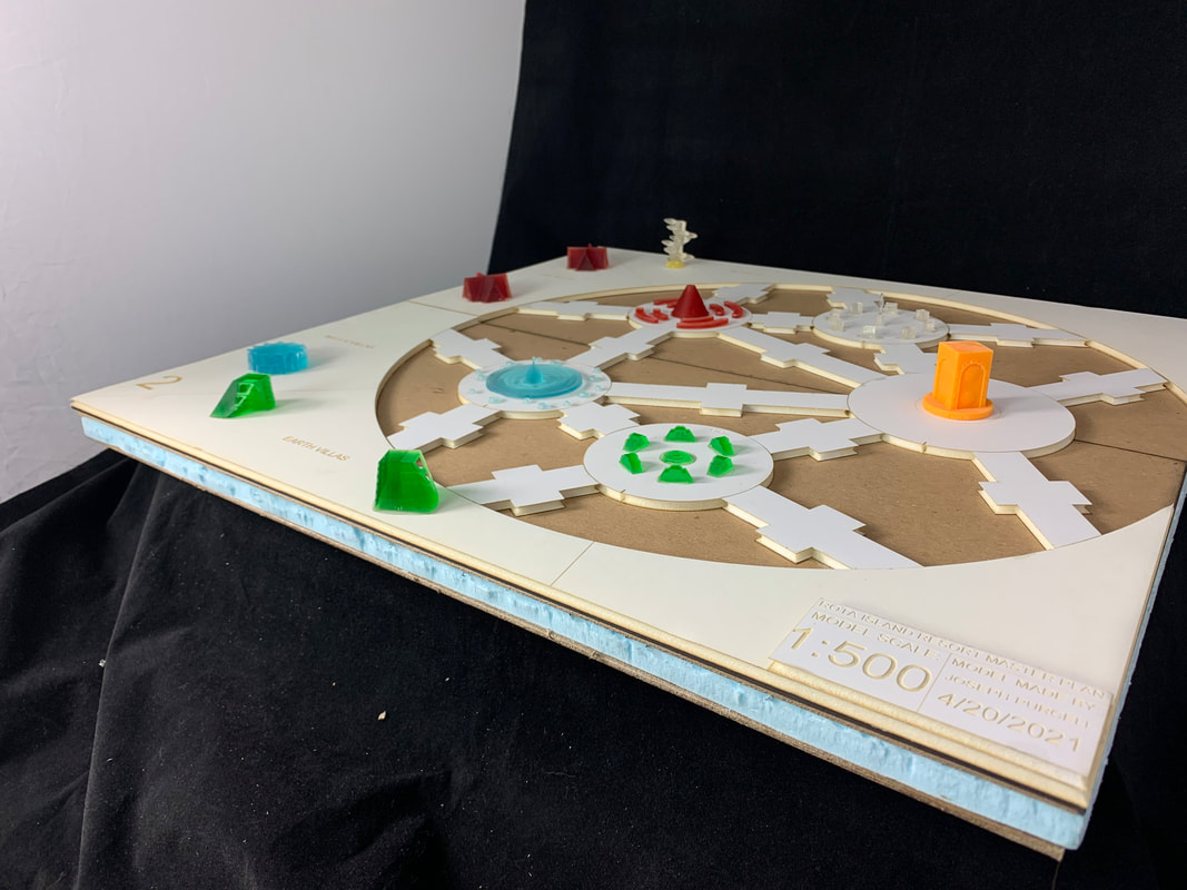
The images above are of my model of the community/garden area and the villa area of my resort. The model is at 1:500 scale, the base of the model is comprised of laser cut chip board and foam core. The colorful components on top of the model were 3d printed on an Elegoo Mars Pro resin printer and using a different color of translucent resin for each respective element (blue for water, red for fire, green for earth, clear for air, and yellow for central.)
Folly Models
Earth Folly:
|
This is a resin printed model of my earth folly, it was printed on an Elegoo Mars Pro resin 3d printer. This larger version of the model (along with the larger versions of the other folly models) was made to both be used for photographs, and to be able to hand around to judges or other observers/passersby of the project. These models are not in scale with one another, as they had to be printed as big as possible in order to best withstand being constantly handled by other people and moved around for display and photographs.
If you wish to know more about this particular folly and its evolution, please scroll up to the "Folly Design and Development" section of my page. |
|
Water Folly:
|
This is the larger scale resin model for the water folly.
If you wish to know more about this particular folly and its evolution, please scroll up to the "Folly Design and Development" section of my page. |
|
Fire Folly:
|
This is the larger scale resin model of the fire folly.
If you wish to know more about this particular folly and its evolution, please scroll up to the "Folly Design and Development" section of my page. |
|
Air Folly:
|
This is the larger scale resin model of the air folly.
If you wish to know more about this particular folly and its evolution, please scroll up to the "Folly Design and Development" section of my page. |
|
Villa Models:
Earth Villa:
|
This is a slide show of the hand cut 1:8th scale model of the earth villa (made out of chipboard), the 1:1 scale floorplans made in Revit, the elevations of both the outside and inside of the villa (in 3:16 scale), and finally, the models made in fusion 360 which I used for both 3d printing and diagrams.
The slanted sides are to represent hills/mountains, the overhangs and balconies are to represent caves, the multiple floors are to represent different earth layers.
|
|
Water Villa:
|
This is a slide show of the hand cut 1:8th scale model of the water villa (made out of chipboard), the 1:1 scale floorplans made in Revit, the elevations of both the outside and inside of the villa (in 3:16 scale), and finally, the models made in fusion 360 which I used for both 3d printing and diagrams.
The round shape is to represent puddles/lakes the single room on the bottom floor and the six rooms are to represent the fact that water can take on many different forms (water, ice, steam, mist, vapor, etc.) The winding curve along the rim of the villa is to represent a winding and bending river.
|
|
Fire Villa:
|
This is a slide show of the hand cut 1:8th scale model of the fire villa (made out of chipboard), the 1:1 scale floorplans made in Revit, the elevations of both the outside and inside of the villa (in 3:16 scale), and finally, the models made in fusion 360 which I used for both 3d printing and diagrams.
The design of this villa is based off of the shape of a burning campfire, the criss-cross shape of the villa is representative of the piled up logs of a campfire and the slanted A-frame style roofs of the wings of the building are to represent the flames. I feel that this design also works due to the fire villa being the smallest of the four elemental villas, that the campfire based design help complements the warm coziness of living in the villa.
|
|
Air Villa:
|
This is a slide show of the hand cut 1:8th scale model of the air villa (made out of chipboard), the 1:1 scale floorplans made in Revit, the elevations of both the outside and inside of the villa (in 3:16 scale), and finally, the models made in fusion 360 which I used for both 3d printing and diagrams.
Each floor of the villa will have a single pod on the outside, the round shape of the pod is to symbolize a cloud. The spiral arrangement of the external pods is based off of a tornado. the outer wall of each pod would have windows, giving the guests a wonderful view of the entire resort, this would also give the illusion that the person watching the view is floating in the air.
|
|
