Architect Study
|
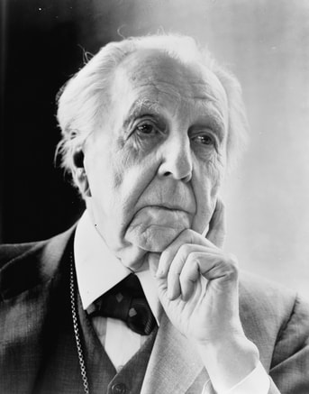
Frank Lloyd Wright (Mini Bio)
Frank Lloyd Wright, born on June 8, 1867, was an American architect best know for the creation of the prairie-style home. In his early adulthood, he dropped out of the University of Wisconsin and moved to Chicago to become and architect. Throughout his career, Wright endeavored to incorporate the natural landscape of a site into his designs-- and supposedly succeeded with his many wide, flat prairie style homes he built in the Midwest. Arguably, his most iconic build is Taliesin, Wright's home and studio in Wisconsin, and its sister in Arizona-- Taliesin West. Over his lifetime, Wright built Taliesin three times after two fires destroyed the building. One, in 1914, killed his wife while the other, in 1925, was caused by an electrical fire. |
Concept Drawing
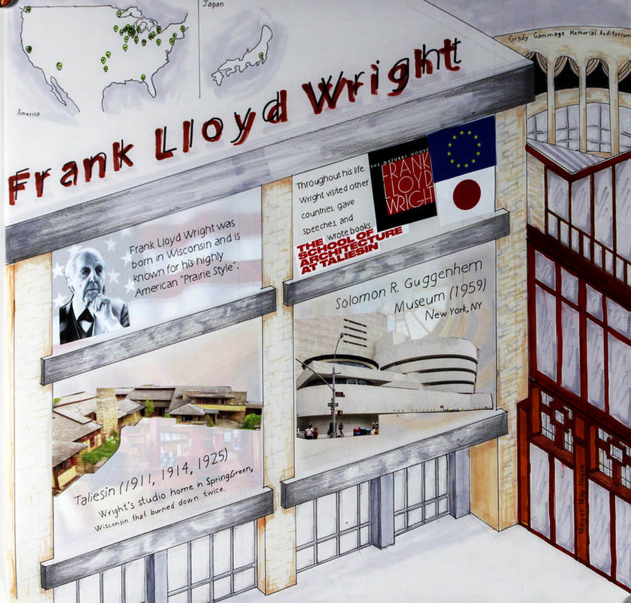
For my concept drawing of Frank Lloyd Wright, I focused on incorporating the symmetry and patterns often found in some of his most memorable works. The left structure was based off part of the mock-up replica of the Imperial hotel-- formerly located in Japan but was torn down in 1968. To the right, I rendered as many of his buildings, mostly his prairie-style houses, as I could.
Throughout the whole concept drawing, I kept the coloring in accordance with tan/beige, grey, and his almost-signature burnt red that he used throughout many of his works. I also made sure to emphasize Wright's use of floor-to-ceiling windows as walls by including the Meyer May house (bottom right), the Herbert Jacobs house (middle), and the Elam house (top right).
Project 01- Fibonacci Cube
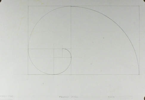
Fibonacci Spiral
Seen to the right is my Fibonacci spiral drawing. It is based on the Fibonacci sequence of adding one number with the one directly before it in the sequence (0,1,1,2,3,5,8,13,21...) The sequence was applied to the drawing by finding the center of a 12x18 in. paper, then measuring a 1x1 in. square to the bottom left of the intersection. From there, I created new squares based on the Fibonacci sequence. The spiral was created with a compass adjusted so that the radius was set to the length of one of the cube sides.
This exercise was done as a prerequisite to the Fibonacci Cube model that we worked on throughout the rest of the semester.
Drawings and Models
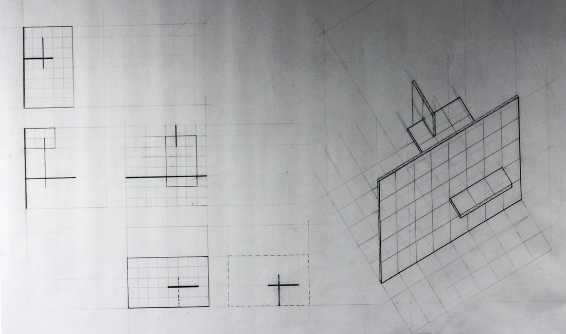
The final drawing for the three plane Fibonacci model I later chose to turn into the Fibonacci cube. Shows orthographic projections
(all on the left at 1/2 scale) of the model including the overhead roof top view( right middle) , elevations for the front (middle left), the left (top most), and right (bottom left) as well as a slice of the model (bottom right). Shows a praline drawing of the model at full scale.
|
Three-Plane Study
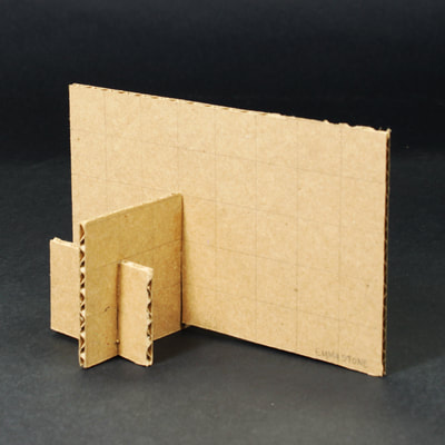
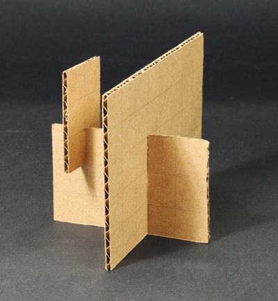
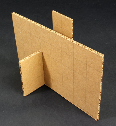
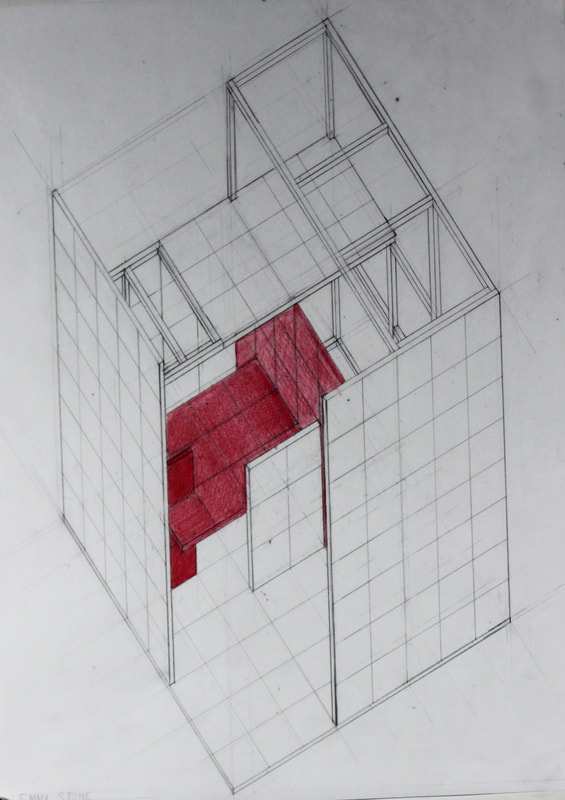
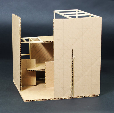
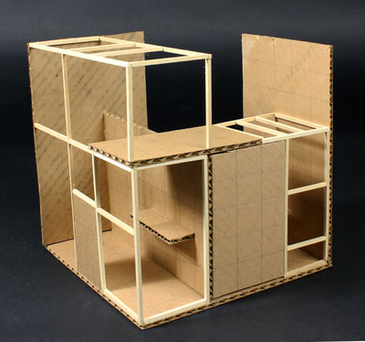
The Three-Plane study was designed to teach the analysis of different useful spaces. I built three unique models from three cardboard planes that were 2x3 in., 3x5 in., and 5x8 in. Without much suggestion on direction, I assembled them randomly. then put them in a white 8x8x8 in. foam-core cube with a grid on the bottom. By putting them in this cube, I could see the different spaces each formed depending on where in the cube the model was placed. I like the the third model (see the drawing above) because of its division of space into three usable spaces, which the other two did not create as well. The two models in the pictures above were the two that I thought formed weaker, less usable spaces (the model I did choose is shown in the drawing above). From there , I added more places (all with the same dimensions listed above) and 1/8" basswood sticks to create my final cube model (seen below and in the drawing to the right). |
Final Cube Model
For the final model, I created an undefined primary space and a defined secondary space within the model. The primary, undefined space sits in front of the secondary space where the open corner is. The secondary space sits behind the primary space. It can be best seen in the left picture where the two 2x3 planes enclose a smaller space. In the right most picture, you can see the secondary space is further enclosed by 1/8 in, basswood sticks.
My most intentional decision within this model was to leave the top plane (what could be a roof) open. By leaving the top undefined, the primary space remains more undefined and smoothly blends into the secondary space.
Project 02- DMZ Duplex
Design
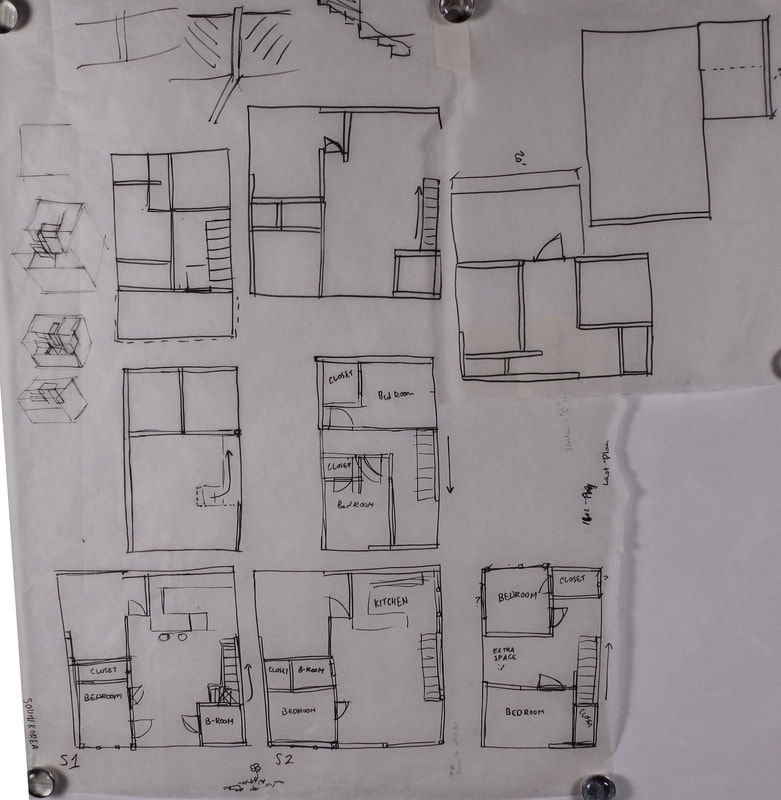
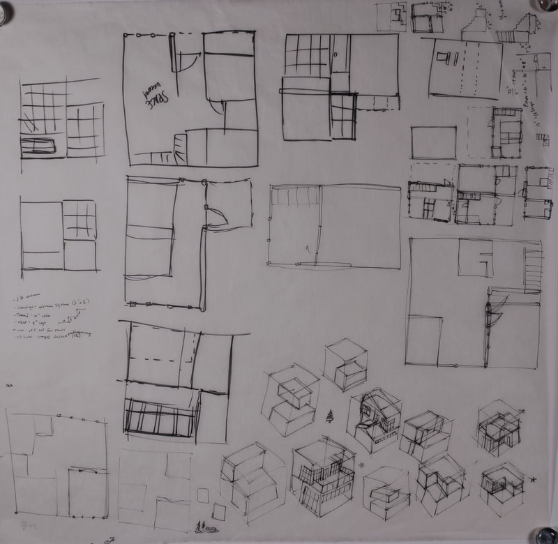
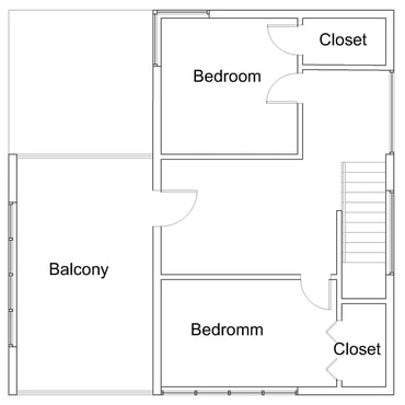
I first began the design process by making modifications to the Fibonacci cube project from the first half of the semester. After some initial internal debate, I decided to keep the two vertical places that created the open corner. From there, I choose to use that corner to make my house into more of an 'L' shape.
From the first model, I did try to keep some of the same openings as windows so that the same sense of openings and space would be preserved in the design of the house itself.
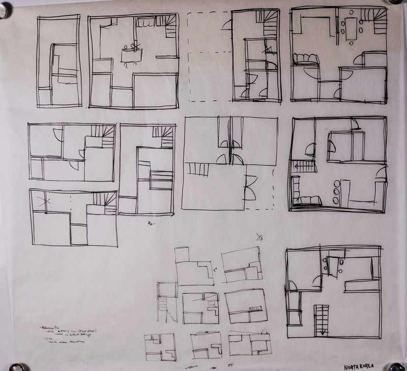
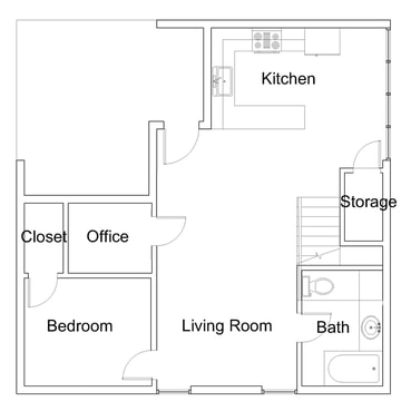
In contrast, the North Korean unit was much more difficult to develop. Since the second was unit was a new design, I spent much more time working out a design that i felt worked practically and culturally, hence the two sketch papers (center and right).
|
North Korea Unit
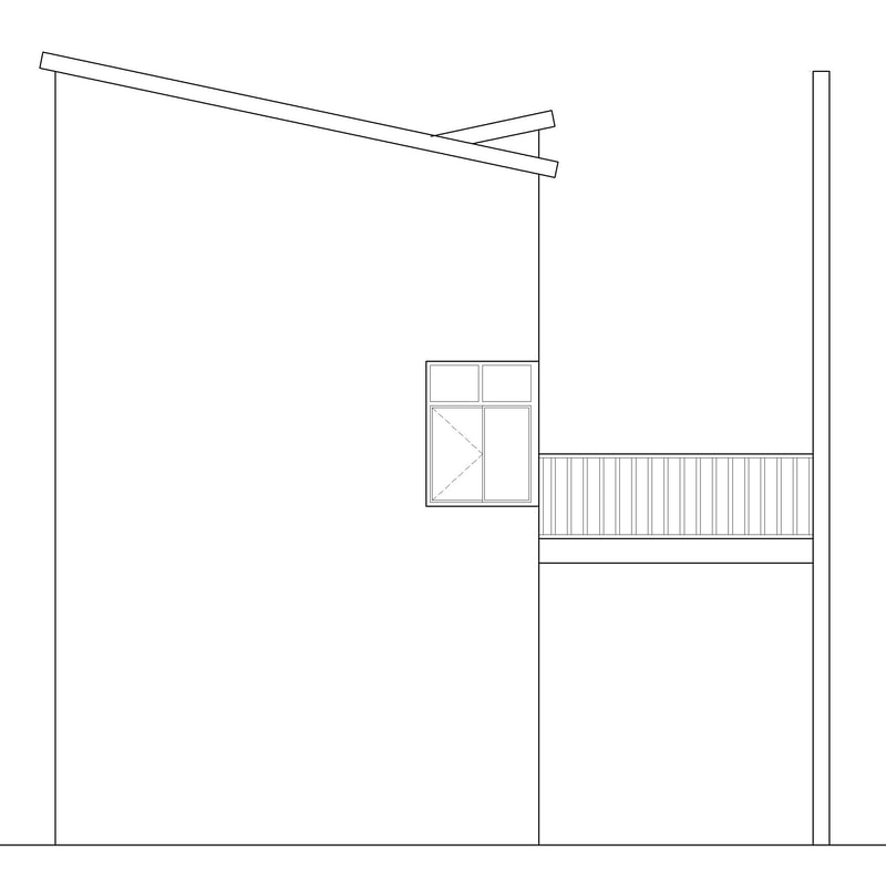
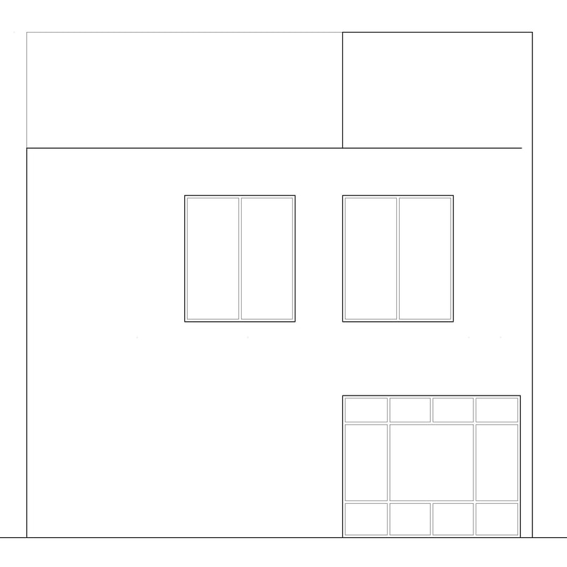
From the design process, I settled on a plan with a combination of more closed off spaces. The large windows in the living and dining rooms were meant to introduce a new, unusual element to the North Koreans. but, to mitigate the openness, i rotated the whole house on the site so that these large windows were primarily facing the short sides of the lot so that the overall flow through the house is blocked. |
|
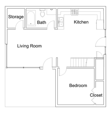
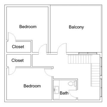
South Korea
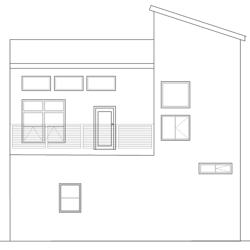
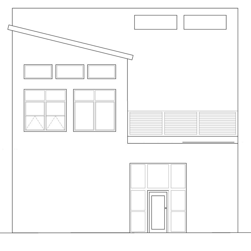
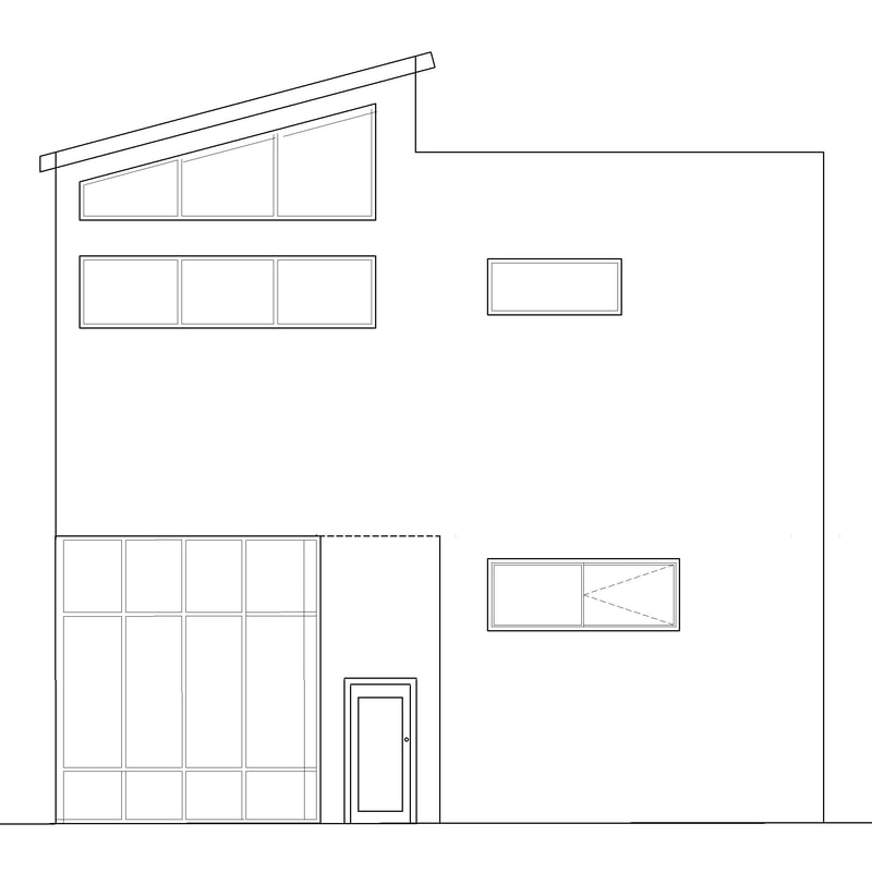
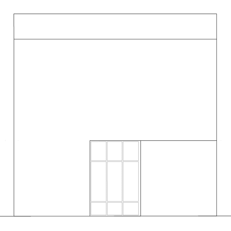
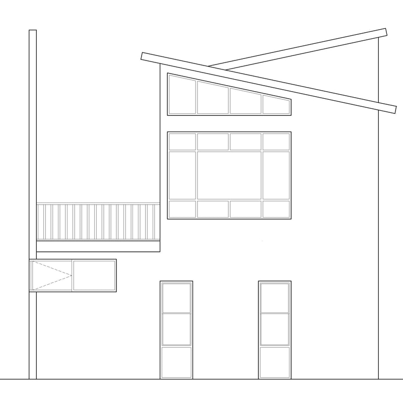
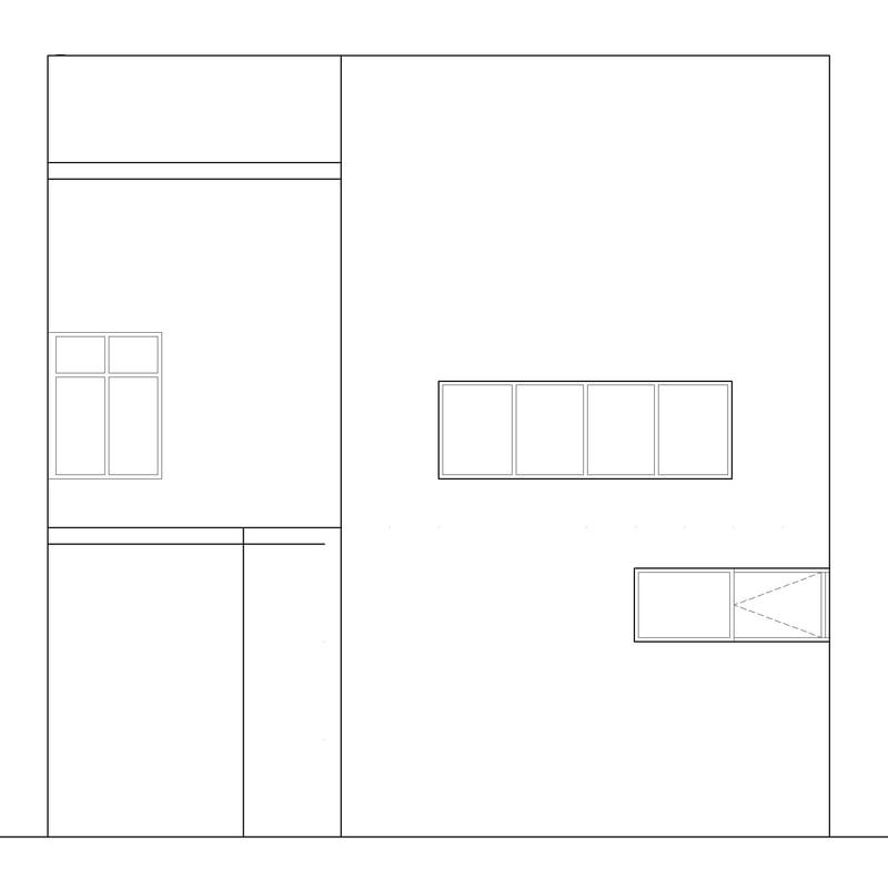
From the original cube model,I decided it best matched a south Korean house because of its potential for a more open concept space more akin to a South Korean apartment. Most of the bedrooms and living spaces have large windows that take up entire walls. |
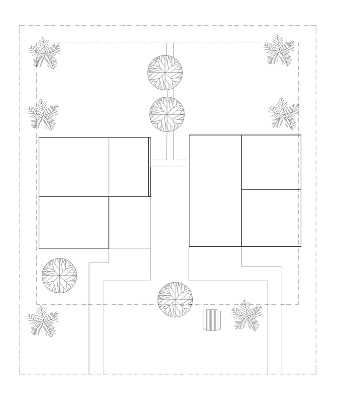 Site Drawing: South Korea unit on left; North Korea unit on right
Site
the plan for the site was to create a space that could be shared by both families in the front and a more private space for each family in the back.
In the front yard, I planned on placing a relaxation/ eating area. by placing this in the front, I hoped to encourage interaction between the to families and the rest of the neighborhood.
for the backyard, I wanted to give each family their own individual outdoor space without completely dividing the yards. So, instead of placing a regular fence, i decided to place a dens bush. It would be short enough to easily see over, but it would still provide a clear definition for the two backyards.
Post-presentation, a suggestion was made to instead have planters separating the yards. By doing this, it would further break down the division between the two families while still creating separate spaces for each unit.
Final Model
